
Adjustment method of real-time data time label, upper computer and distributed control system

A technology of time stamping and real-time data, applied in the direction of comprehensive factory control, comprehensive factory control, electrical program control, etc., can solve the problems of inaccuracy, trend curve deviation, disconnection, etc.

Active Publication Date: 2015-11-18
ZHEJIANG SUPCON TECH
View PDF5 Cites 0 Cited by
  • Summary
  • Abstract
  • Description
  • Claims
  • Application Information

AI Technical Summary

Problems solved by technology

[0005] In view of this, the present invention provides a real-time data time label adjustment method, a host computer and a distributed control system, which are used to solve the trend graph drawn by the host computer due to the inaccuracy of the time label sent by the lower computer in the prior art. For problems such as flattening, disconnection, and trend curve shifting, the technical solution is as follows:

Method used


Image

  • Adjustment method of real-time data time label, upper computer and distributed control system
  • Adjustment method of real-time data time label, upper computer and distributed control system
  • Adjustment method of real-time data time label, upper computer and distributed control system

Examples


Embodiment 1

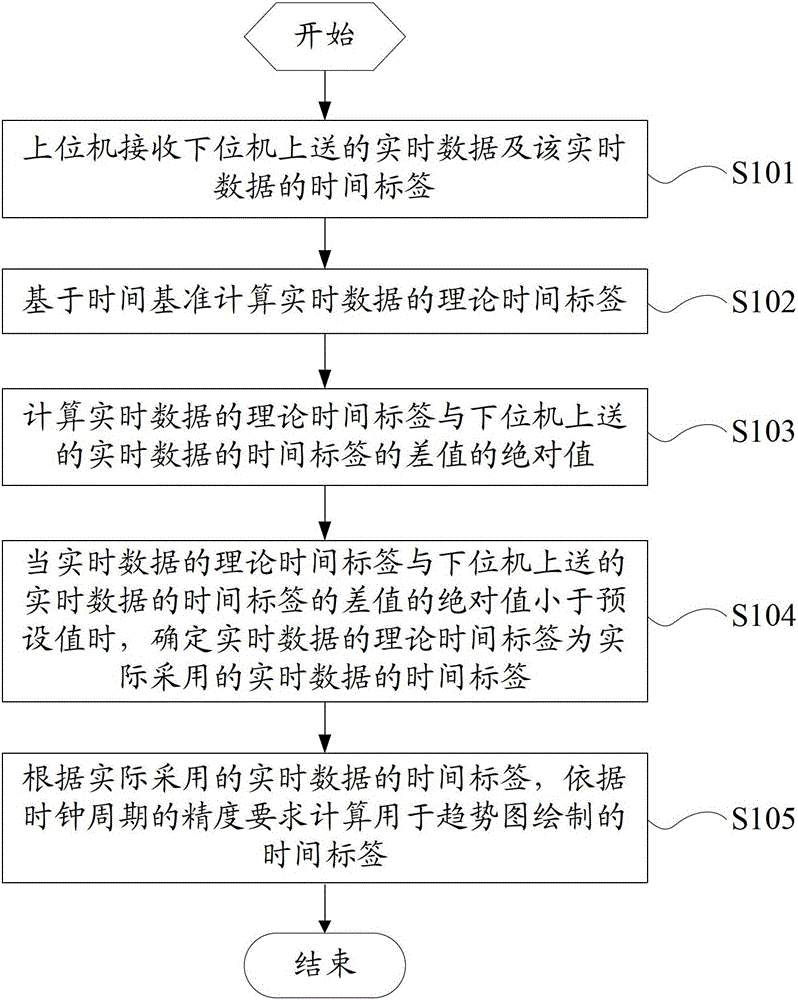
[0039] see figure 1 , which is a schematic flowchart of a method for adjusting a real-time data time tag provided in Embodiment 1 of the present invention, the method may include:

[0040] Step S101: The upper computer receives the real-time data and the time stamp of the real-time data sent by the lower computer.

[0041] Step S102: Calculate the theoretical time stamp of the real-time data.

[0042] Step S103: Calculate the absolute value of the difference between the theoretical time stamp of the real-time data and the time stamp of the real-time data sent from the lower computer.

[0043] Step S104: When the absolute value of the difference between the theoretical time stamp of the real-time data and the time stamp of the real-time data sent from the lower computer is less than the preset value, determine that the theoretical time stamp of the real-time data is the time stamp of the real-time data actually used.

[0044] Step S105: According to the time label of the real...

Embodiment 2

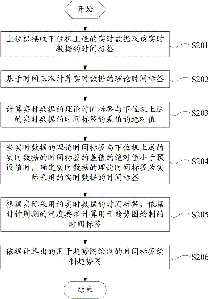
[0047] see figure 2 , which is a schematic flowchart of a method for adjusting a real-time data time tag provided in Embodiment 2 of the present invention, the method may include:

[0048] Step S201: The upper computer receives the real-time data and the time stamp of the real-time data sent by the lower computer.

[0049] Step S202: Calculate the theoretical time stamp of the real-time data.

[0050] In this embodiment, the calculation of the theoretical time stamp of the real-time data specifically includes: adding the time stamp used for drawing the trend graph in the previous period, the time reference and the clock cycle to obtain the theoretical time stamp of the real-time data.

[0051] Set the theoretical time stamp of real-time data to T t , the clock period is T, and the time label used for trend graph drawing is T p , the time base is b, then, T t = T of the previous cycle p +b+T.

[0052] It should be noted that if the host computer receives data for the fir...

Embodiment 3

[0077] see Figure 4 , is a schematic structural diagram of a host computer provided in Embodiment 3 of the present invention, the host computer may include: a data receiving unit 101, a first computing unit 102, a second computing unit 103, a judging unit 104, a determining unit 105 and a third computing unit 106 . in:

[0078] The data receiving unit 101 is used for receiving the real-time data and the time stamp of the real-time data sent from the lower computer.

[0079] The first computing unit 102 is configured to calculate a theoretical time tag of real-time data.

[0080] The second calculation unit 103 is used to calculate the absolute value of the difference between the theoretical time stamp of the real-time data and the time stamp of the real-time data sent from the lower computer.

[0081] The judging unit 104 is configured to judge whether the absolute value of the difference between the theoretical time stamp of the real-time data and the time stamp of the re...


PUM


Abstract

The application provides an adjusting method of a real-time data time label, a host computer and a dispersion control system. The host computer is used for receiving real-time data and a time label of the real-time data submitted by a secondary computer, for calculating a theoretic time label of the real-time data, and for calculating the absolute value of difference between the theoretic time label of the real-time data and the time label of the real-time data submitted by the secondary computer; when the absolute value of difference is less than a preset value, the theoretic time label of the real-time data is taken as the practical time label of the real-time data; a time label for drawing a tendency chart is calculated according to the requirement on precision of a clock period on the basis of the practical time label of the real-time data. The adjusting method of the real-time data time label, the host computer and the dispersion control system provided by the application can be used for drawing the tendency chart under the situation that the impact deviation on the time label of network load, CPU (Central Processing Unit) load, inaccuracy in timing period, clock synchronization of small amplitude and the like is in a preset range.

Description

technical field [0001] The invention relates to the technical field of industrial control, in particular to a real-time data time label adjustment method, a host computer and a distributed control system. Background technique [0002] In the industrial control airspace, the distributed control system (DCS, Distributed Control Systems) is divided into upper computer and lower computer, wherein, the upper computer is the operator station, and the lower computer is the control station. [0003] Normally, the lower computer sends VQT data to the upper computer with a basic cycle of 1 second, where V (Value) in VQT represents the value of the data, Q (Quality) represents the quality code of the data, and T (TimeStamp) represents the data generation time. Under normal circumstances, the data received by the HMI software has a fixed cycle, which is usually 1 second. However, in reality, the accuracy of the timing cycle of the lower computer will be affected by the CPU load and net...

Claims


Application Information

Patent Timeline
Patent Type & Authority Patents(China)
IPC IPC(8): G05B19/418
CPCY02P90/02
Inventor 陈挺阮波孔垂亮谭彰
Owner ZHEJIANG SUPCON TECH
Learn More