
Extrusion units especially for plastics

An extrusion device, plastic technology, applied in the field of manufacturing tubular body, plastic extrusion device

Active Publication Date: 2016-07-13
乔治·马卡年吉马克公司
View PDF6 Cites 0 Cited by
  • Summary
  • Abstract
  • Description
  • Claims
  • Application Information

AI Technical Summary

Problems solved by technology

Consequently, as a result, there is a flow resistance that adversely affects the constant delivery of the two materials, which are not extruded in a uniform manner

Method used


Image

  • Extrusion units especially for plastics
  • Extrusion units especially for plastics
  • Extrusion units especially for plastics

Examples


Embodiment Construction

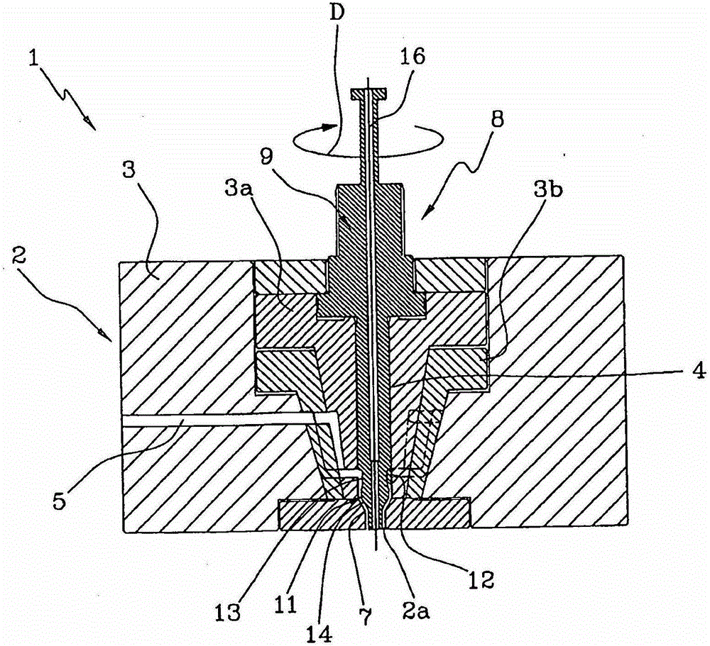
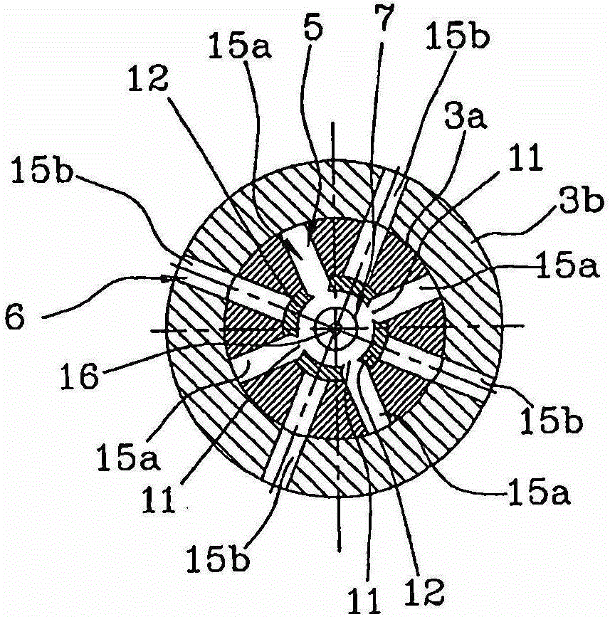
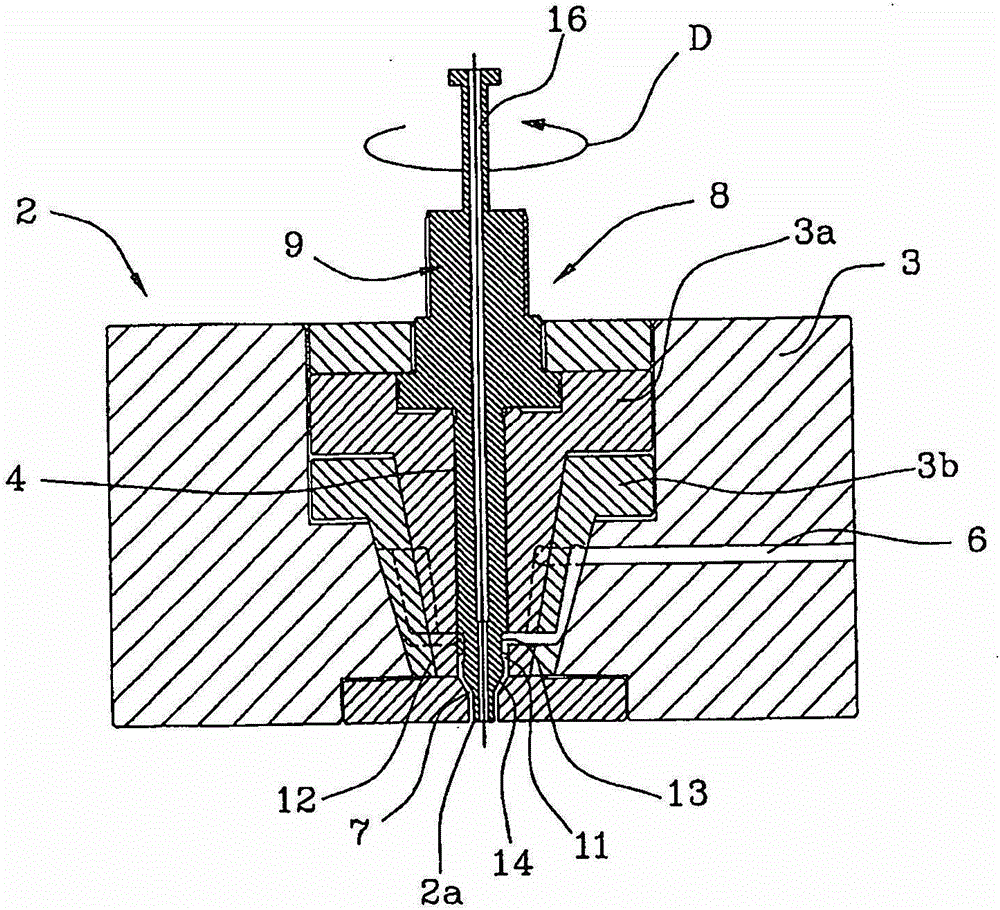
[0040] With particular reference to the drawings, an extrusion device according to the invention has been indicated generally by the reference number 1 .

[0041] In detail, the device 1 comprises, arranged in its lower part, an extrusion head 2 having injection nozzles 2a for delivering at least one plastic M1 , M2 to be extruded.

[0042] In particular, refer to figure 1 with 2 , it should be noted that the extrusion head 2 has a support body 3 for a pair of annular parts 3a, 3b, which are coaxial with each other and inserted into each other. The innermost annular portion 3a has a longitudinal cavity 4 delimiting said spray nozzle 2a at its corresponding end. It should be noted that each annular portion 3a, 3b cooperating with said support body 3 defines a corresponding channel for the passage of the plastic to be extruded.

[0043] In particular, as figure 1 As shown in , the innermost annular portion 3a has a first channel 5 for feeding the first plastic material M1 to...


PUM


Abstract

An extrusion device, in particular for plastics, comprising: an extrusion head (2) having nozzles (2a) for injecting at least one plastic (M1, M2); formed in said extrusion head ( 2) in the first channel (5) for supplying the first plastic (M1) to the injection nozzle (2a); the second channel (β) formed in the extrusion head (2) for for feeding said spray nozzle (2a) with a second plastic (M2); and a selection element (8) arranged adjacent to said spray nozzle (2a) and capable of being switched between a first operating state and a second operating state A switch is made wherein in the first operating state the selection element second channel (6) causes the first plastic (M1) to be fed via the first channel (5), in the second operating state the selection element first channel (5) The second plastic (M2) is fed through the second channel (6).

Description

technical field [0001] The invention relates to an extrusion device especially for plastics. [0002] In more detail, the present invention relates to a device for manufacturing a tubular body by extruding two materials different from each other, which are respectively arranged on the tubular body in an alternating manner. In other words, the invention is particularly useful for alternately extruding two plastics different from each other so as to form a continuous tubular body. Background technique [0003] It is known that an extrusion device consists of an extrusion head defining a corresponding injection nozzle for molten plastic. [0004] The spray nozzle has a generally annular extension adapted to define the tubular shape of the final product. In order to maintain the hollow structure of this final product, a blowpipe can be used, which is arranged in the middle of the annular nozzle and is adapted to supply air to the interior of the material as it is extruded from...

Claims


Application Information

Patent Timeline
Patent Type & Authority Patents(China)
IPC IPC(8): B29C47/04B29C47/24B29C47/28B29C48/19B29C48/09B29C48/21B29C48/31B29C48/32B29C48/33B29C48/34B29C48/49
CPCB29C48/19B29C48/33B29C48/34B29C48/09B29C48/49B29C2948/9259B29C2948/92514B29C2948/92885B29C2948/92904B29C48/21
Inventor G·马卡年
Owner 乔治·马卡年吉马克公司
Learn More