Centrifugal pumps in parallel jointed series

A centrifugal pump and conjoined technology, applied in the field of parallel conjoined centrifugal water pumps, can solve the problems of large axial thrust, impact wear, damage, etc., achieve performance improvement, eliminate frictional resistance, and reduce hidden dangers of accidents

Inactive Publication Date: 2005-06-15
赵其林
View PDF0 Cites 1 Cited by
  • Summary
  • Abstract
  • Description
  • Claims
  • Application Information

AI Technical Summary

Problems solved by technology

[0002] The multi-stage single-suction segmented centrifugal pump (called D-type pump) that is widely used now has a large axial thrust, and the axial thrust is balanced by the balance disc method. However, when the pump is started, there is a post-related phenomenon due to the balance force, which will cause Short-term impact and abrasion, damage after excessive wear

Method used


Image

  • Centrifugal pumps in parallel jointed series
  • Centrifugal pumps in parallel jointed series

Examples


Embodiment 1

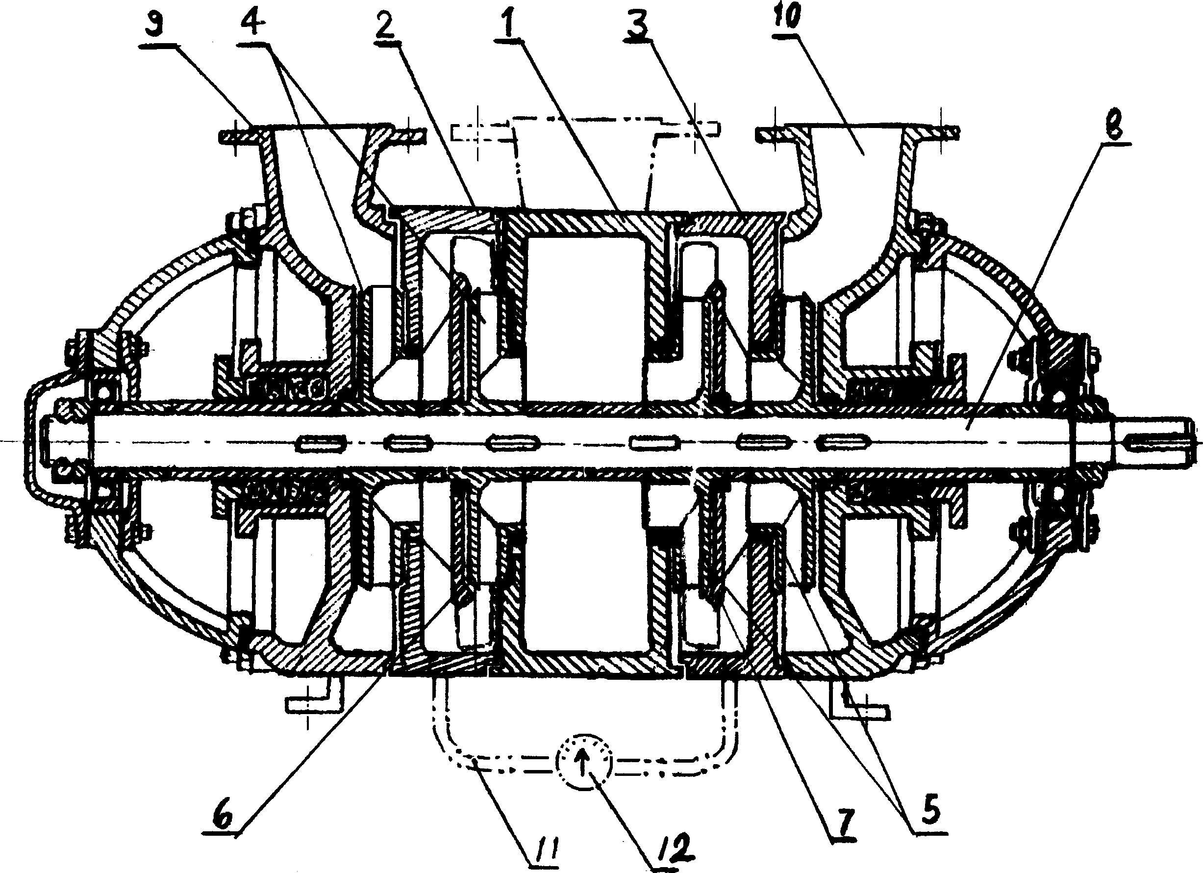
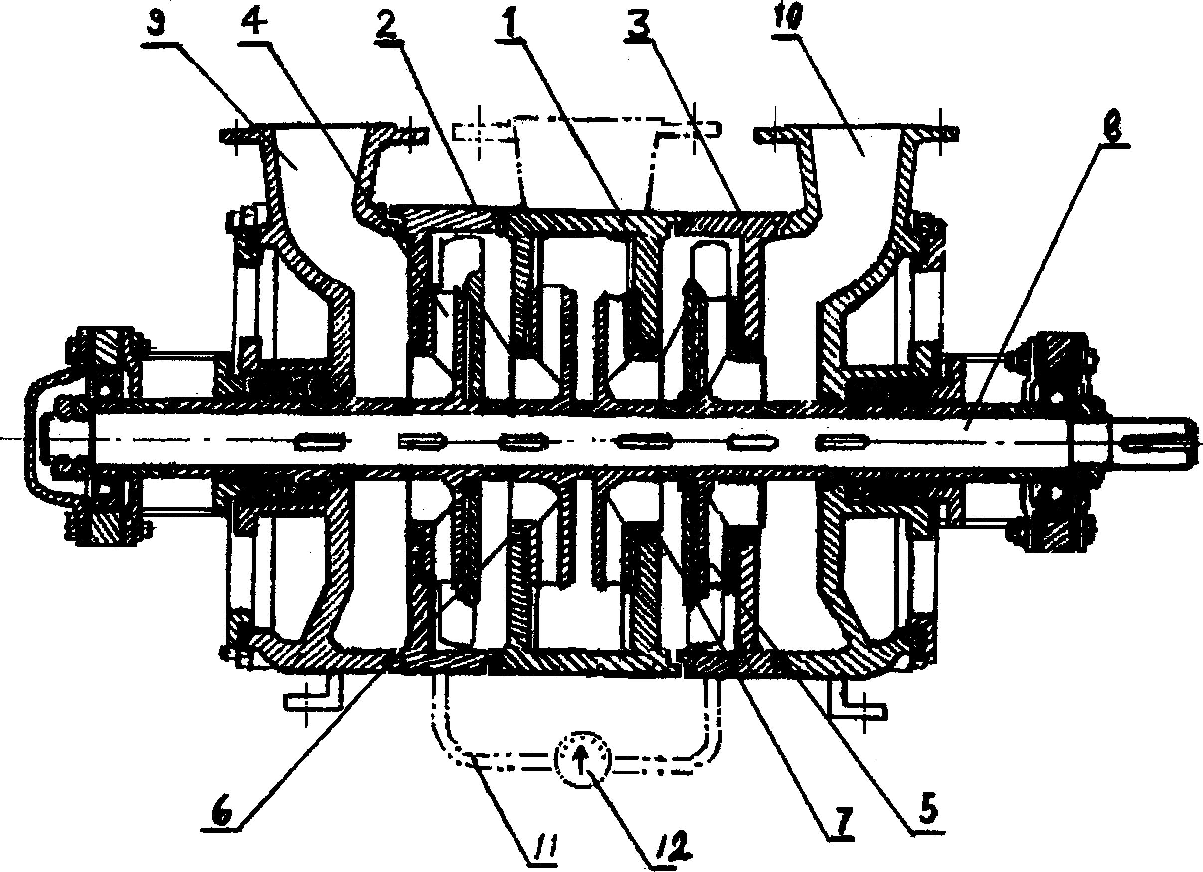
[0009] Embodiment 1, the present invention includes a pump casing, a pump bracket, a pump shaft 8 set on the pump supporting frame and connected to the power device, and a bearing set on the pump shaft and matched with the pump bracket. It is characterized in that it is provided with a water outlet The left water outlet section 9 and the right water outlet section 10 are respectively provided with water outlet chambers around the pump shaft, the left water outlet section 9 is fixedly connected with the left bracket of the pump, the right water outlet section 10 is fixedly connected with the right bracket of the pump, and the left water outlet section 9 and the right water outlet section 10 There are pump shaft mounting holes on the outside of the pump shaft respectively. The outside of the left water outlet section 9 and the right water outlet section 10 form a dynamic seal fit with the pump shaft sleeve set on the pump shaft 8 through the pump shaft installation holes. The left...

Embodiment 2

[0011] Embodiment 2, the left middle section 2 and the right middle section 3 are respectively set between the left water outlet section 9 and the right water outlet section 10 and the water inlet section 1, and the left middle section 2 and the right middle section 3 are provided with a middle section cavity surrounding the pump shaft, and the middle section cavity The pump shaft 8 is sleeved with the left impeller 4 and the right impeller 5 respectively. In the production process, the water inlet section 1 connected to the water pipe should have a cross-sectional area of ​​the water inlet pipe not less than the sum of the cross-sectional areas of the two outlet pipes. The left impeller 4 and the right impeller 5 are respectively installed on the pump shaft 8, the left guide vane 6 and the right guide vane 7 are respectively installed in each middle section, and each middle section and left impeller and guide vane are the same as the D-type pump. The size of the right impelle...

Embodiment 3

[0012] Embodiment 3, the left middle section 2 and the right middle section 3 are respectively set between the left water outlet section 9 and the right water outlet section 10 and the water inlet section 1, and the left middle section 2 and the right middle section 3 are provided with a middle section cavity surrounding the pump shaft, and the middle section cavity One or more left impellers 4 and right impellers 5, and left guide vanes 6 and right guide vanes 7 are set respectively. All the other are with embodiment 2, refer to figure 1 .


PUM


Abstract

The invention relates to a kind of parallel body-connected series centrifugal pump. It belongs to a water pump. It includes pump shell, pump supporting frame, pump shaft cover-mounted on the pump supporting frame and connected with power device and bearing cover-mounted on the pump shaft and matched with pump supporting frame. Besides, it also includes the components of water inlet, water intake section, water intake cavity, water outlet, water discharge section, water discharge cavity and blade wheel, etc. Said invention also provides the concrete structure of the above-mentioned every component and their connection method.

Description

technical field [0001] The invention relates to a water pump, in particular to a parallel connected centrifugal water pump. Background technique [0002] The multi-stage single-suction segmented centrifugal pump (called D-type pump) that is commonly used now has a large axial thrust, and the axial thrust is balanced by the balance disc method. Short-term impact and abrasion can cause hazards after excessive wear and tear. Contents of the invention [0003] The object of the present invention is to provide a kind of high-efficiency, energy-saving, less breakdown, durable parallel conjoined series centrifugal pump basically without axial thrust and without balancing device. [0004] The purpose of the present invention is achieved through the following technical solutions: it includes a pump casing, a pump bracket, a pump shaft 8 that is sleeved on the pump support frame and connected with the power device, and a bearing that is sleeved on the pump shaft and matches the pum...

Claims


Application Information

Patent Timeline
Patent Type & Authority Applications(China)
IPC IPC(8): F04D1/10
Inventor 赵其林
Owner 赵其林
Why Eureka
Try Eureka