
Transmission self-locking device for rotary Z shaft of spray-painting device
A self-locking device, Z-axis technology, applied in the direction of the injection device, etc., can solve the problem of not easy to lock, and achieve the effect of good self-locking function
- Summary
- Abstract
- Description
- Claims
- Application Information
AI Technical Summary
Problems solved by technology
Method used
Image

Examples
Embodiment Construction
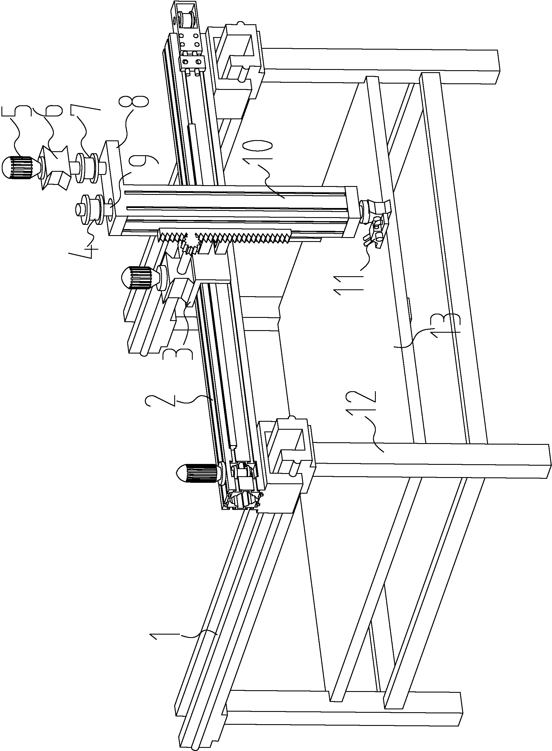
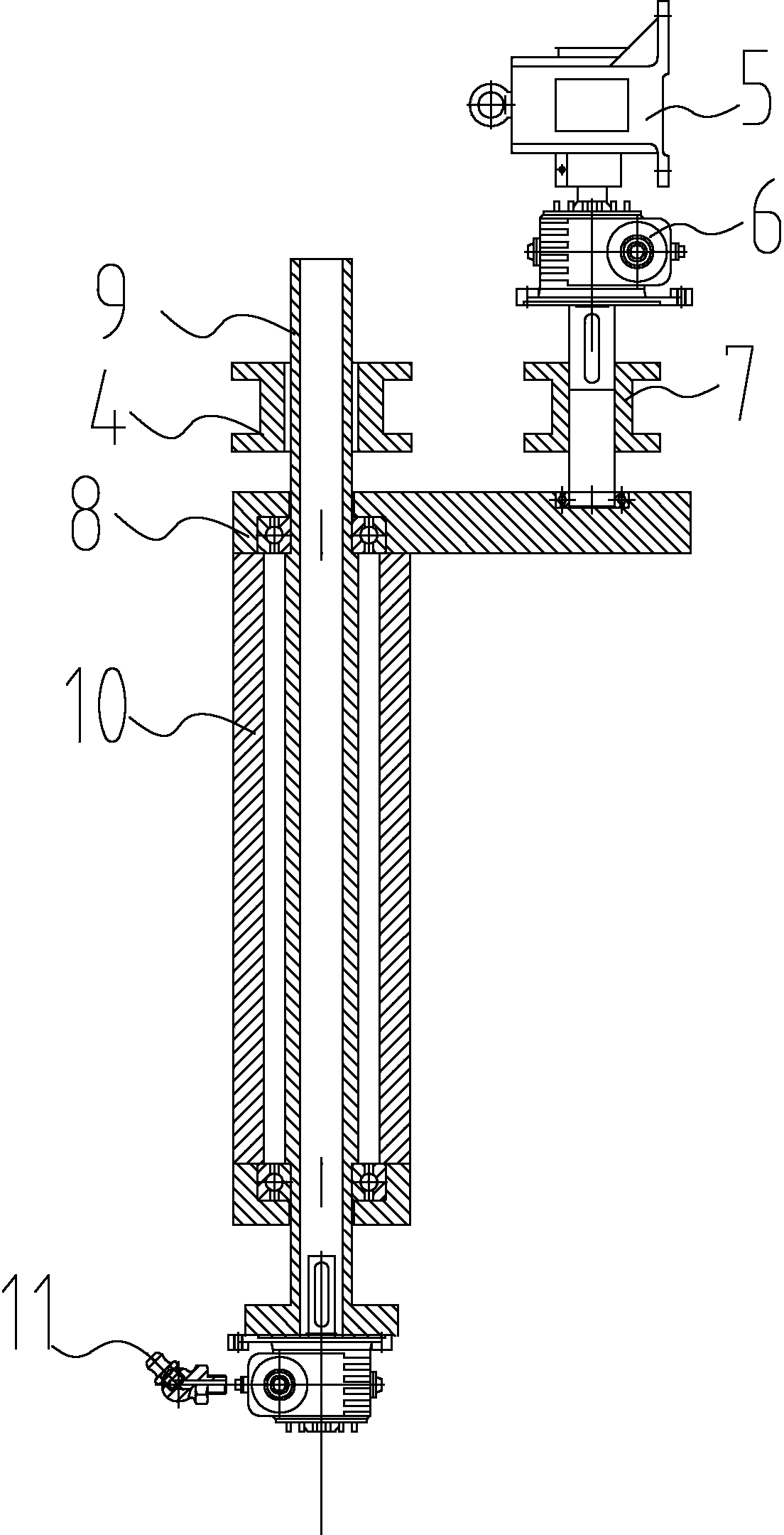
[0011] Such as figure 1 with figure 2 As shown, a transmission self-locking device for rotating the Z-axis of a paint spraying device includes a rectangular bottom frame 12, a horizontal bottom plate 13 is provided on the rectangular bottom frame 12, and a pair of X beams 1 are provided on the rectangular bottom frame 12 , Each X beam 1 is provided with a linear guide rail, each guide rail is matched with a sliding block, two sliding blocks are provided with a Y beam 2, and each X beam 1 is also provided with a transmission belt. One end of a transmission belt is connected with a corresponding sliding block, and the other end is matched with a corresponding pulley on the X beam 1. The two pulleys are connected by a transmission shaft. A servo motor and a corresponding The Y beam 2 is provided with a movable frame 3 that can move in the Y direction. The movable frame 3 and the Y beam 2 are also connected by a linear guide and a sliding block, and are provided at one end of t...
PUM
 Abstract
Description
Claims
Application Information