Check patentability & draft patents in minutes with Patsnap Eureka AI!

Self-locking reinforced earth retaining wall block and retaining wall system

A reinforced soil and self-locking technology, which is applied in water conservancy projects, artificial islands, underwater structures, etc., can solve the problems of insufficient bonding force between surface blocks, difficulty in forming a resultant force, and high requirements for foundation bearing capacity. The wall installation structure is flexible and changeable, the bearing capacity requirement is reduced, and the effect of prolonging the service life

Active Publication Date: 2016-01-06
重庆永固建筑科技发展有限公司
View PDF9 Cites 0 Cited by
  • Summary
  • Abstract
  • Description
  • Claims
  • Application Information

AI Technical Summary

Problems solved by technology

The existing retaining wall block is a standardized rectangular shape. Due to the limitations of the existing retaining wall block and installation structure, the following problems have always existed in the construction of reinforced earth retaining walls using reinforced materials, and effective solve:
[0003] 1. Existing prefabricated retaining walls cannot form walls with certain or multiple slopes
[0004] 2. The existing reinforced earth retaining wall cannot be reliably connected with reinforced materials of various shapes and properties
[0005] 3. The existing reinforced earth retaining wall cannot achieve overall reliable connection through its own interlocking, and the bonding force between the surface blocks is not ideal enough to form a resultant force
[0006] 4. The installation structure of the existing reinforced earth retaining wall is single, and it is impossible to form different and beautiful wall shapes through multiple combination installations
[0007] 5. The existing retaining wall panels are made of ordinary plain concrete, which is heavy and not conducive to factory production. At the same time, the bearing capacity of the foundation is also required to be high

Method used


Image

  • Self-locking reinforced earth retaining wall block and retaining wall system
  • Self-locking reinforced earth retaining wall block and retaining wall system
  • Self-locking reinforced earth retaining wall block and retaining wall system

Examples


Embodiment Construction

[0033] The present invention will be further described below in conjunction with accompanying drawing.

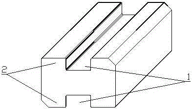
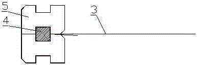
[0034] The self-locking reinforced earth retaining wall face block of the present invention can be found in figure 1 , it can be seen from the figure that the retaining wall block is in the form of a rectangular cylinder as a whole, and the upper surface and the lower surface of the retaining wall block are respectively provided with rectangular self-locking grooves 1 along the length direction, and the depth of the self-locking grooves 1 on the upper and lower surfaces is same. The parts of the upper and lower surfaces located on both sides of the self-locking groove 1 form self-locking ribs 2, so this retaining wall surface block has four self-locking ribs 2, which are the self-locking ribs on the inner and outer sides of the upper and lower surfaces, and the outer side refers to the viewing side. , the inner side refers to the filler side. The self-locking groove is l...


PUM


Abstract

The invention discloses a self-locking reinforced soil retaining wall block and a retaining wall system. The retaining wall face block is in the form of a rectangular cylinder as a whole, and the upper surface and the lower surface of the retaining wall face block are respectively provided with rectangular bars along the length direction. Self-locking groove, the depth of the self-locking groove on the upper and lower surfaces is the same, the parts on both sides of the upper and lower surfaces of the self-locking groove form self-locking ribs, the self-locking groove is located in the middle of the upper and lower surfaces and the width of the self-locking groove is equal to the width of the self-locking ribs. The self-locking reinforced soil retaining wall system includes several retaining wall blocks and reinforcing materials of the above-mentioned structure. The retaining wall face blocks are combined in pairs to form an installation unit, and then several installation units are stacked in sequence according to a certain rule to form a retaining wall. . The retaining wall system of the present invention can form walls with certain or multiple slopes as required, the retaining wall is reliably connected to various reinforcement materials, the bonding force between blocks of the retaining wall is large, and the installation structure of the wall is flexible and changeable.

Description

technical field [0001] The invention relates to an earth slope body retaining wall structure, in particular to a self-locking reinforced earth retaining wall block and a retaining wall system formed based on the retaining wall face block, belonging to the technical field of retaining walls. Background technique [0002] Reinforced earth retaining walls are mainly used in the engineering of filling retaining walls in various industries. The current reinforced earth retaining wall system is mainly composed of retaining wall face blocks, reinforcing materials and retaining wall fillers. Blocks of the retaining wall are stacked continuously at a certain height to form a wall, and reinforcement materials are connected to the block of the retaining wall to increase the bearing capacity of the block. The existing retaining wall block is a standardized rectangular shape. Due to the limitations of the existing retaining wall block and installation structure, the following problems h...

Claims


Application Information

Patent Timeline
Patent Type & Authority Patents(China)
IPC IPC(8): E02D29/02
Inventor 朱春笋张祖渝罗锦辉刘家和
Owner 重庆永固建筑科技发展有限公司
Features
  • R&D
  • Intellectual Property
  • Life Sciences
  • Materials
  • Tech Scout
  • Unparalleled Data Quality
  • Higher Quality Content
  • 60% Fewer Hallucinations
Learn More