Permanent magnet synchronous reluctance motor testing device and testing method thereof
A reluctance motor and test device technology, which is applied in the direction of motor generator testing, measuring device casing, etc., can solve the problems that the motor noise cannot be adjusted to the lowest value, lack of a better test method, etc., and achieves flexible and changeable installation structure. The effect of wide range and small calculation error
- Summary
- Abstract
- Description
- Claims
- Application Information
AI Technical Summary
Problems solved by technology
Method used
Image

Examples
Embodiment 1
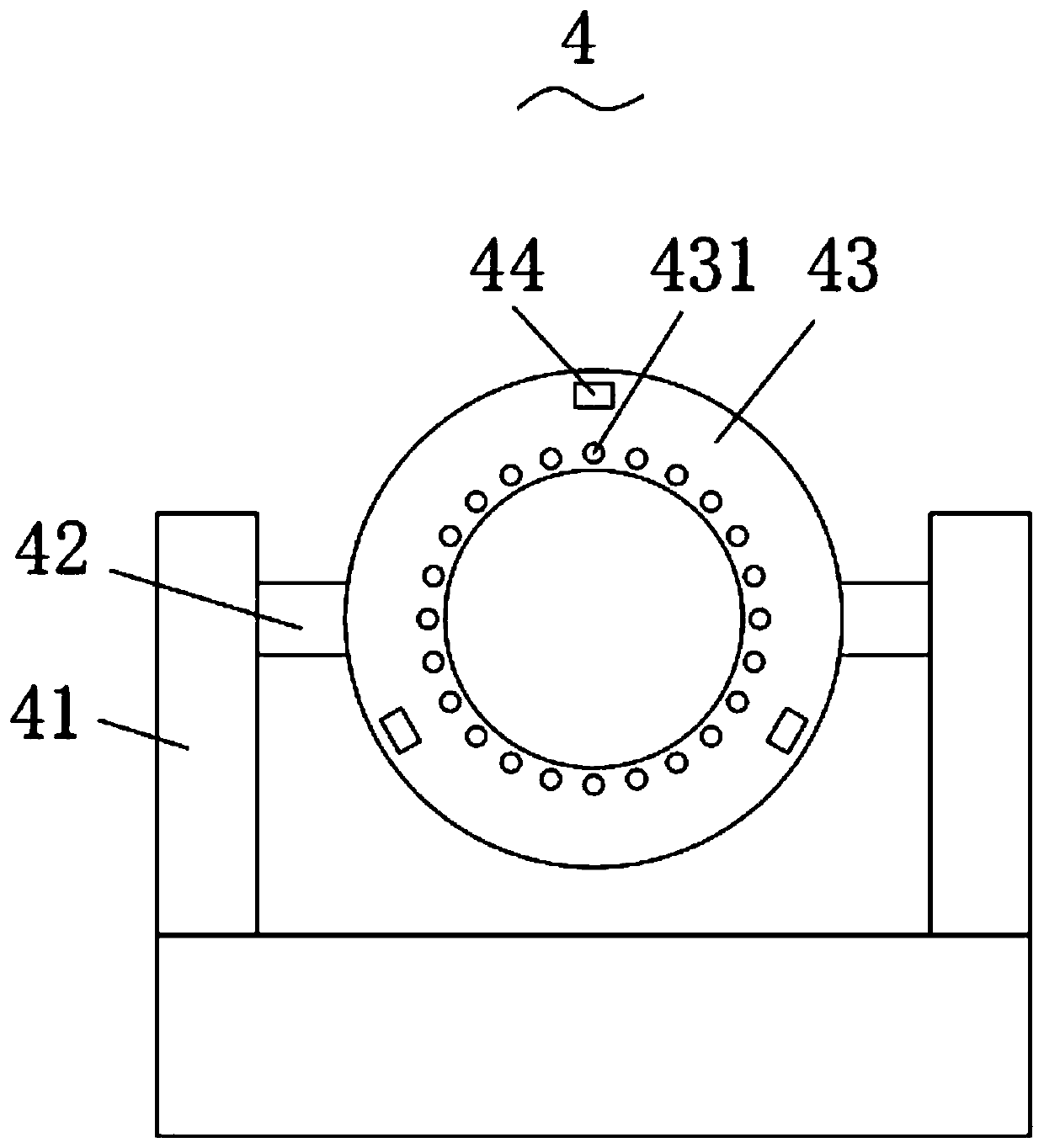
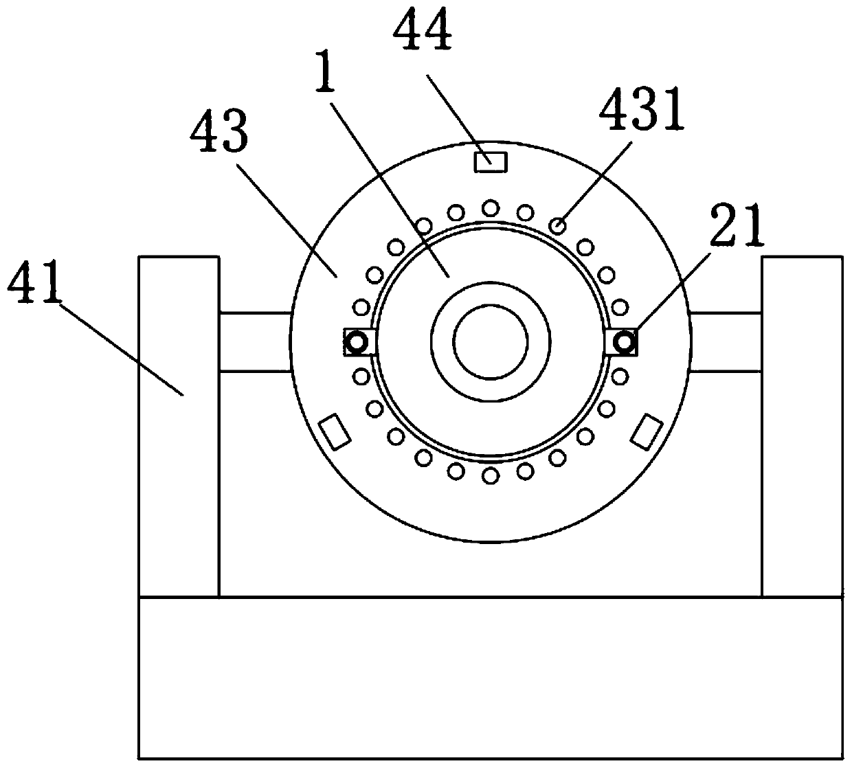
[0051] Such as figure 1 as shown, figure 1 It is a structural schematic diagram of the first embodiment of the permanent magnet synchronous reluctance motor test device shown in the present invention;
[0052] (1) Use soildworks simulation modeling;
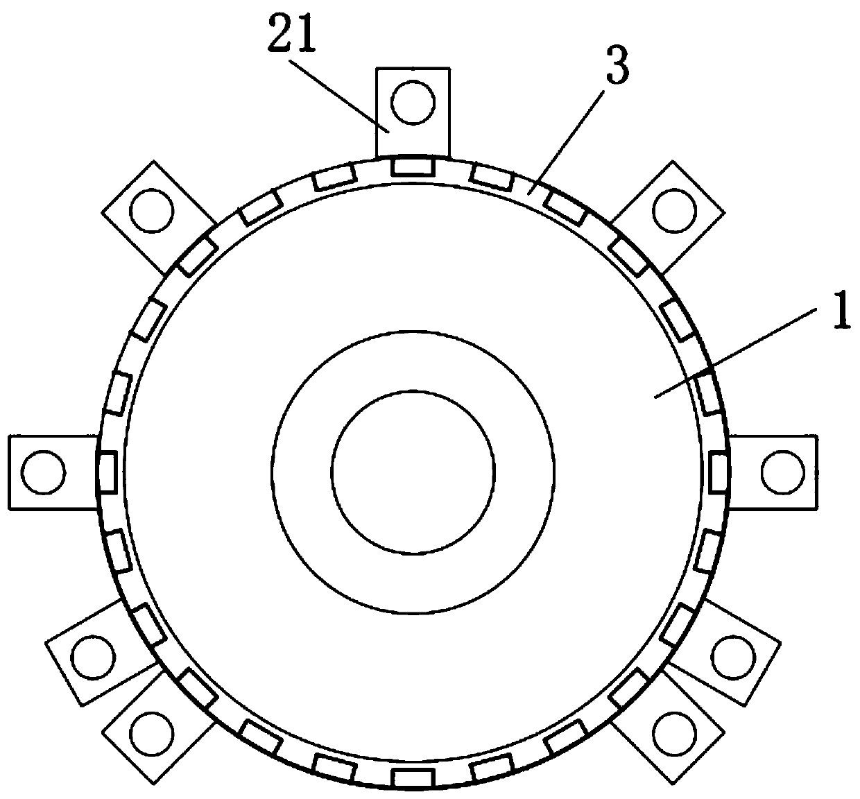
[0053]Establish a simulation model of the standard motor 1, the mounting ring 3, and two positioning plates 21;
[0054] Determine the coordinates of the center of mass of the standard motor model;
[0055] Assemble the mounting ring model with the standard motor model so that the two centroids are on the same vertical line; when making full use of the rotational flexibility coupling of the generator installation system, it is necessary to correct the centroid of the positioning plate until the two centroids are on the same vertical line on, thereby effectively reducing noise;
[0056] Install 2 positioning plate models on the mounting ring model to form the test motor model, and ensure that the 2 positioning plate models and...
Embodiment 2
[0076] Such as Figure 6 as shown, Figure 6 It is the structural representation of the second embodiment of the permanent magnet synchronous reluctance motor test device shown in the present invention;
[0077] (1) Use soildworks simulation modeling;
[0078] Establish a simulation model of the standard motor 1, the mounting ring 3, and the three positioning plates 21;
[0079] Determine the coordinates of the center of mass of the standard motor model;
[0080] Assemble the mounting ring model with the standard motor model so that the centers of mass of both are on the same vertical line;
[0081] Install 3 positioning plate models on the mounting ring model to form the test motor model, and ensure that the 3 positioning plate models and the standard motor model are located on the same vertical line;
[0082] (2) Prepare the test motor by 3D printer according to the test motor model;
[0083] (3) The test motor is fixed on the connecting ring 43; the motor is plugged in...
Embodiment 3
[0101] Such as Figure 7 as shown, Figure 7 It is the structural representation of the third embodiment of the permanent magnet synchronous reluctance motor test device shown in the present invention;
[0102] (1) Use soildworks simulation modeling;
[0103] Establish a simulation model of the standard motor 1, the mounting ring 3, and the four positioning plates 21;
[0104] Determine the coordinates of the center of mass of the standard motor model;
[0105] Assemble the mounting ring model with the standard motor model so that the centers of mass of both are on the same vertical line;
[0106] Install 4 positioning plate models on the mounting ring model to form the test motor model, and ensure that the 4 positioning plate models and the standard motor model are located on the same vertical line;
[0107] (2) Prepare the test motor by 3D printer according to the test motor model;
[0108] (3) The test motor is fixed on the connecting ring 43; the motor is plugged into...
PUM
 Abstract
Description
Claims
Application Information
 - R&D
- Intellectual Property
- Life Sciences
- Materials
- Tech Scout
- Unparalleled Data Quality
- Higher Quality Content
- 60% Fewer Hallucinations
Browse by: Latest US Patents, China's latest patents, Technical Efficacy Thesaurus, Application Domain, Technology Topic, Popular Technical Reports.
© 2025 PatSnap. All rights reserved.Legal|Privacy policy|Modern Slavery Act Transparency Statement|Sitemap|About US| Contact US: help@patsnap.com