
Eureka
For R&D, Eureka makes reading and utilizing patents & technical documents easy.
Eureka AIR
Designed for self-driven R&D workflows. Generate viable solutions, solve complex R&D challenges, empower your innovation with AI.

Eureka Materials
Designed for material experts only. Revolutionize your material R&D, from search, analyze, to developing new materials.

TechResearch
Generate reliable direction feasibility study reports for your R&D in just a few steps.

TechSeek
Discover and master advanced knowledge NOW. Basics, ideas, possibilities, all at once.

TechMind
As an expert in R&D Theories, TechMind can generates customized viable solutions instantly.

TechRisk
Analyze your overall solution with one click, know your potential R&D risks in advance.

TechMonitor
Get weekly tech updates, stay abreast of the latest tech innovations and key insights.
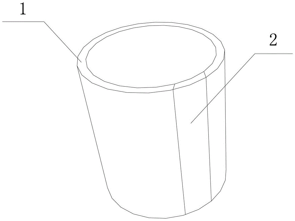
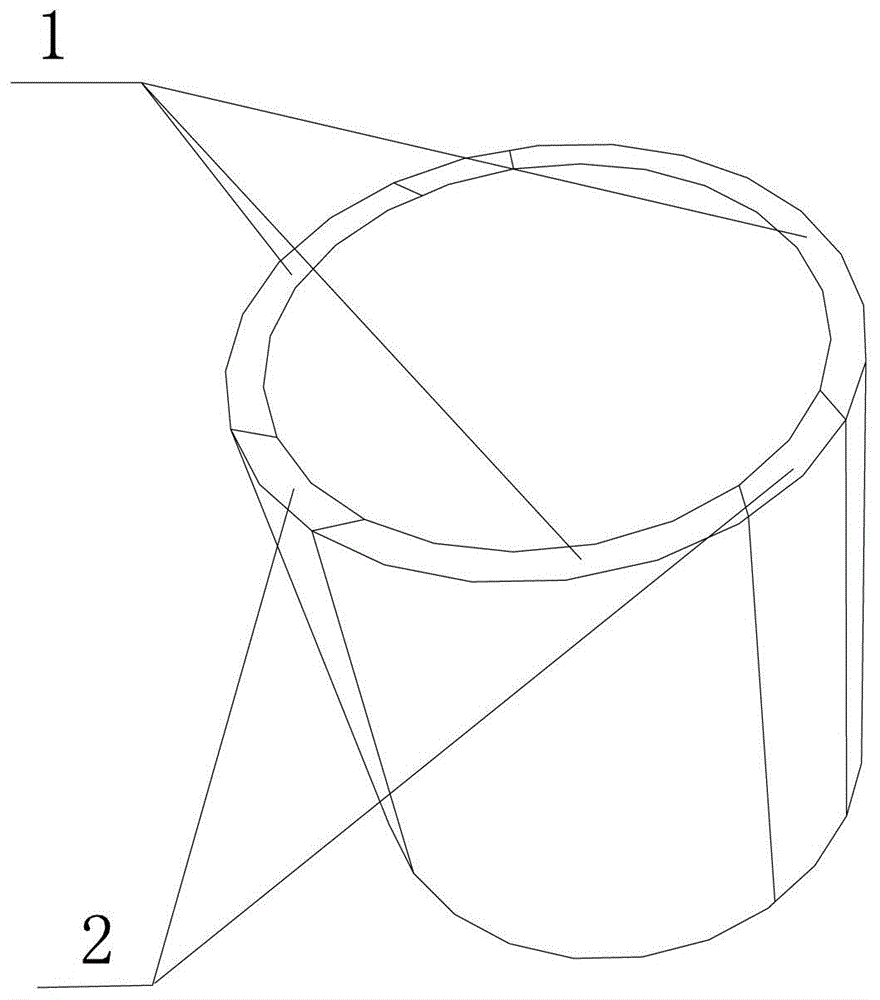
A protective sleeve for high voltage cables
A technology for protecting bushings and high-voltage cables, which is applied in the field of power equipment, can solve problems such as power loss, insufficient strength, and potential safety hazards, and achieve the effects of reducing heat generation, improving safety performance, and reducing impact
- Summary
- Abstract
- Description
- Claims
- Application Information
AI Technical Summary
Problems solved by technology
Method used
Image

Examples
Embodiment Construction
[0013] In order to further understand the invention content, characteristics and effects of the present invention, the following examples are given, and detailed descriptions are as follows in conjunction with the accompanying drawings:
[0014] see figure 1 , figure 2 , a protective sleeve for high-voltage cables, including a metal sleeve 1 and a welded pipe 2; wherein: the side wall of the metal sleeve 1 is provided with a broken seam, the welded pipe 2 is arranged in the broken seam, the welded pipe 2 and the welded pipe 2 The metal sleeves 1 are welded together. One or more broken seams can be set on a metal casing 1, such as figure 1 As mentioned above, a broken seam is provided on a metal casing 1, and there are two schemes during use. The first scheme is to place the welded pipe 2 in an underground groove, and then place the welded pipe 2 in the broken seam After the welding is completed, put the high-voltage cable into the metal casing 1; plan two, first place the ...
PUM
 Abstract
Description
Claims
Application Information
 - R&D Engineer
- R&D Manager
- IP Professional
- Industry Leading Data Capabilities
- Powerful AI technology
- Patent DNA Extraction
Browse by: Latest US Patents, China's latest patents, Technical Efficacy Thesaurus, Application Domain, Technology Topic, Popular Technical Reports.
© 2024 PatSnap. All rights reserved.Legal|Privacy policy|Modern Slavery Act Transparency Statement|Sitemap|About US| Contact US: help@patsnap.com