Electric shaking table

An electric shaker and shaker technology, applied in the field of electric shaker, can solve the problems of reduced production capacity and unsatisfactory shaking reaction effect, etc.

Inactive Publication Date: 2013-10-23
KUNSHAN JINXIN BIOTECH
View PDF0 Cites 0 Cited by
  • Summary
  • Abstract
  • Description
  • Claims
  • Application Information

AI Technical Summary

Problems solved by technology

[0002] There are many kinds of shakers on the market, most of which are simple in structure but the response effect of shaking is not satisfactory, so people have to test the use effect of the shaker during use, which greatly reduces the production capacity, and a A shaker with simple manipulation and better shaking response effect has become an urgent need for people.

Method used


Image

  • Electric shaking table

Examples


Embodiment Construction

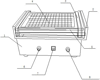
[0009] Such as figure 1 As shown, an electric shaker includes a shaker main body 1, a vibrator 2, a vibrating device 3, a vibrating platform 4, a test tube placement hole 5, a railing 6, a control button 7, a switch 8 and an adjustment button 9, and the vibrator 2 is set on the shaker main body 1, the vibrating device 3 is set on the vibrator 2, the vibrating platform 4 is set on the vibrating device 3, the test tube placement hole 5 is set on the vibrating platform 4, the railing 6 Set on the vibrating platform 4 , the control button 7 , switch 8 and adjustment button 9 are set on the shaker main body 1 .


PUM


Abstract

The invention discloses an electric shaking table which comprises a shaking table main body, a vibrator, a vibration device, a vibration platform, a test tube holding hole, a handrail, a control button, a switch and an adjusting button, wherein the vibrator is arranged on the shaking table main body; the vibration device is arranged on the vibrator; the vibration platform is arranged on the vibration device; the test tube holding hole is arranged on the vibration platform; the handrail is arranged on the vibration platform; and the control button, the switch and the adjusting button are arranged on the shaking table main body. The electric shaking table is simple and easy to understand in operation and control and remarkable in shaking effect.

Description

technical field [0001] The invention relates to an electric shaker. Background technique [0002] There are many kinds of shakers on the market, most of which are simple in structure but the response effect of shaking is not satisfactory, so people have to test the use effect of the shaker during use, which greatly reduces the production capacity, and a A shaker with simple manipulation and better shaking response effect has become an urgent need for people. Contents of the invention [0003] The object of the present invention is to provide an electric shaker. [0004] The technical scheme adopted in the present invention is: [0005] An electric shaker, comprising a shaker main body, a vibrator, a vibrating device, a vibrating platform, a test tube placement hole, a railing, a control button, a switch and an adjustment button, the vibrator is arranged on the shaker main body, and the vibrating device is provided with On the vibrator, the vibration platform is set on t...

Claims


Application Information

Patent Timeline
IPC IPC(8): B01F11/00
Inventor 徐修甲王井义
Owner KUNSHAN JINXIN BIOTECH
Why Eureka
Try Eureka