Fluorescent plate

A fluorescent board and card board technology, applied in the field of fluorescent boards, can solve the problems of large fluorescent boards, limited use, inconvenience, and inconvenient portability, and achieve the effect of small size and easy portability

Inactive Publication Date: 2013-10-23
谢虹
View PDF6 Cites 1 Cited by
  • Summary
  • Abstract
  • Description
  • Claims
  • Application Information

AI Technical Summary

Problems solved by technology

[0003] However, because the fluorescent board is relatively large, it is inconvenient to carry; and the fluorescent board needs to be plugged in before it can be used, which brings great limitations and inconvenience to people's use.

Method used


Image

  • Fluorescent plate
  • Fluorescent plate
  • Fluorescent plate

Examples


Embodiment Construction

[0021] The present invention will be further described below in conjunction with the accompanying drawings and preferred embodiments.

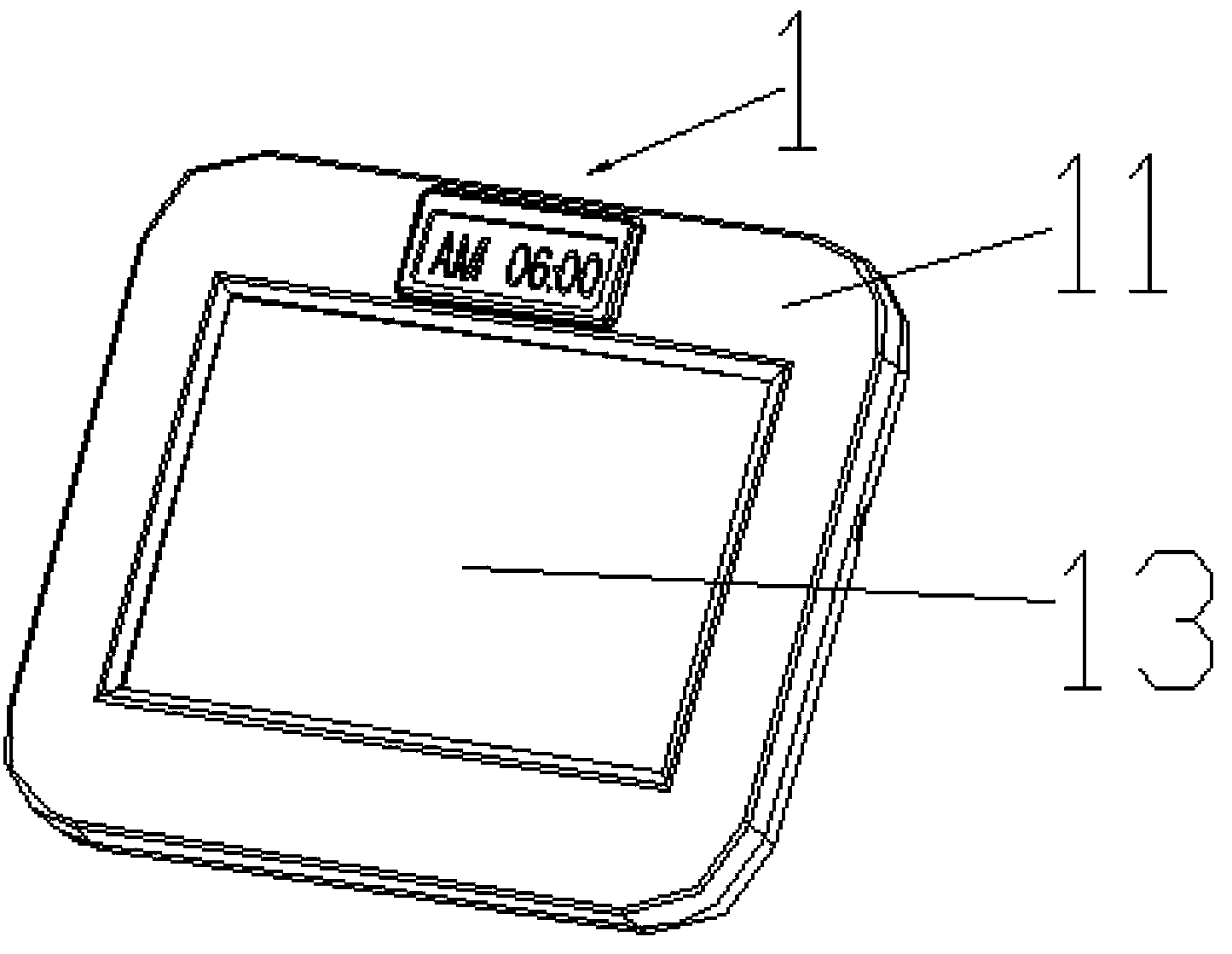
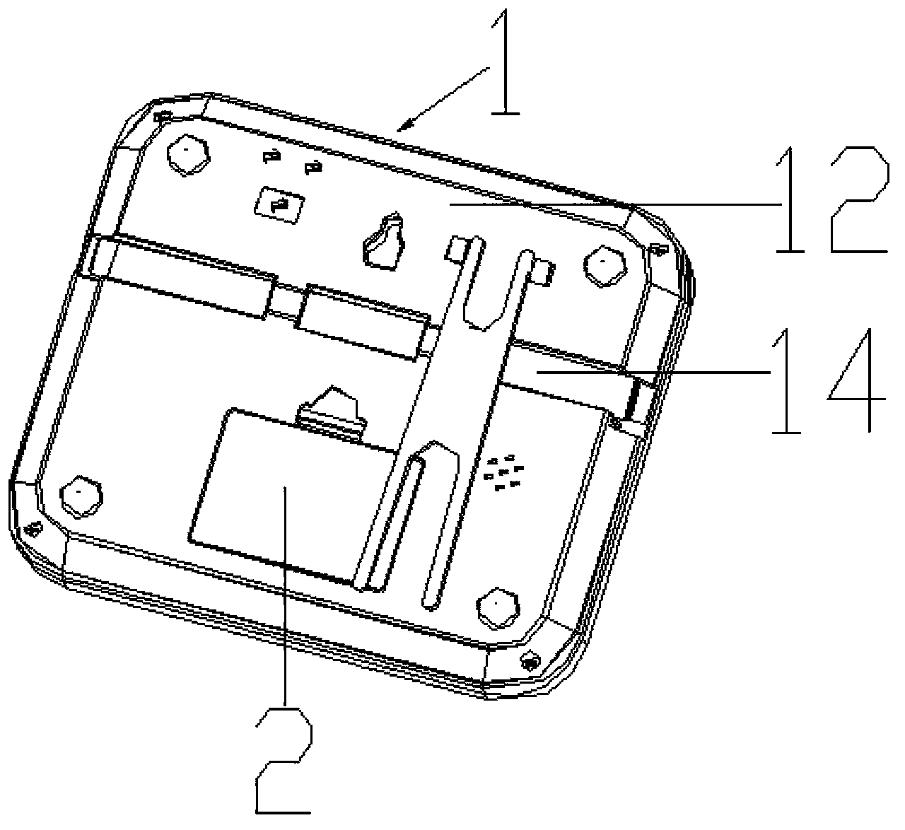
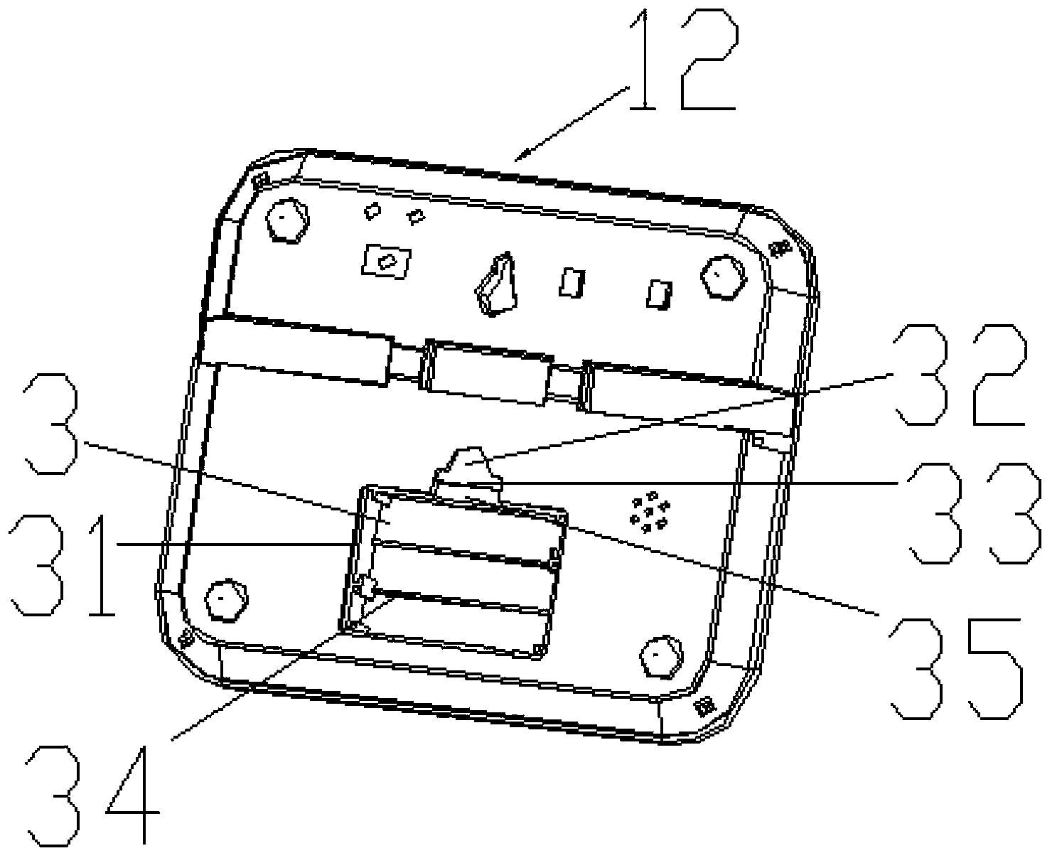
[0022] A fluorescent plate, including a casing and a panel arranged in the casing, and also includes a battery installed in the casing, such as Figure 1 to Figure 4 shown. In the present invention, a battery is installed in the casing, and the battery supplies power to the fluorescent board 1, so the fluorescent board 1 can be used without using a power source, so that the fluorescent board 1 can be used anytime and anywhere; and the fluorescent board 1 is small in size, so it is easy to carry .

[0023] like figure 1 and figure 2 The schematic diagram of the overall structure of the fluorescent plate of the present invention shown; the fluorescent plate 1 of the present invention also includes a highlighter 14 for writing on the panel 13, a circuit board (not shown) arranged on the housing And the LED lamp connected with the circuit boa...


PUM


Abstract

The invention discloses a fluorescent plate which comprises a housing, a panel arranged in the housing, and a battery mounted in the housing. As the battery is mounted in the housing of the fluorescent plate to supply power to the fluorescent plate, the fluorescent plate can be used without a power supply anytime and anywhere; the fluorescent plate is convenient to carry due to small volume.

Description

technical field [0001] The invention relates to the field of household appliances, more specifically, to a fluorescent plate. Background technique [0002] The fluorescent boards currently on the market, also known as fluorescent handwriting boards, LED electronic handwriting fluorescent boards, LED fluorescent boards, electronic fluorescent boards or cable color fluorescent boards, etc., are written on the fluorescent board with a fluorescent pen, plugged in, and passed through the fluorescent screen. The LED high-brightness patch light source on the side of the board shines on the acrylic panel or ultra-white glass panel, and the words written by the highlighter emit different colors and different modes of effects, which are very attractive to the eye. Fluorescent panels are mainly used in: electronics industry, catering industry, communication industry, stationery industry, gift jewelry industry and so on. [0003] However, since the fluorescent board is relatively large...

Claims


Application Information

Patent Timeline
Patent Type & Authority Applications(China)
IPC IPC(8): B43L1/00F21L4/00H01M50/262H01M50/271
CPCB43K23/001B43L1/00B43L1/004Y02E60/10H01M50/262H01M50/271
Inventor 谢虹
Owner 谢虹
Why Eureka
Try Eureka