Three-roller gate movement and three-roller gate running method applying three-roller gate movement

A technology of three-roller gate and movement, applied in the direction of turnstiles, etc., can solve the problems of weak impact resistance, high cost of parts, large volume, etc., to prolong the working life, reduce the size of the movement, and reduce the occupation of equipment. The effect of channel minimization

Active Publication Date: 2013-10-23
DONGGUAN ZKTECO ELECTRONICS TECH
View PDF5 Cites 10 Cited by
  • Summary
  • Abstract
  • Description
  • Claims
  • Application Information

AI Technical Summary

Problems solved by technology

[0007] The invention provides a three-roller gate movement, which aims to solve the problems of weak impact resistance, large volume, easy trailing and high cost of components in the prior art

Method used


Image

  • Three-roller gate movement and three-roller gate running method applying three-roller gate movement
  • Three-roller gate movement and three-roller gate running method applying three-roller gate movement
  • Three-roller gate movement and three-roller gate running method applying three-roller gate movement

Examples


Embodiment Construction

[0037] In order to make the object, technical solution and advantages of the present invention clearer, the present invention will be further described in detail below in conjunction with the accompanying drawings and embodiments. It should be understood that the specific embodiments described here are only used to explain the present invention, not to limit the present invention.

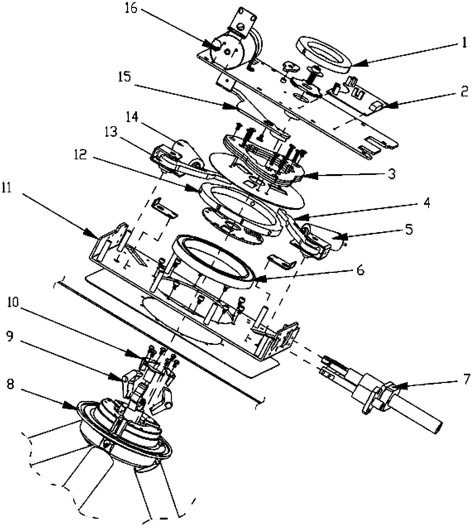
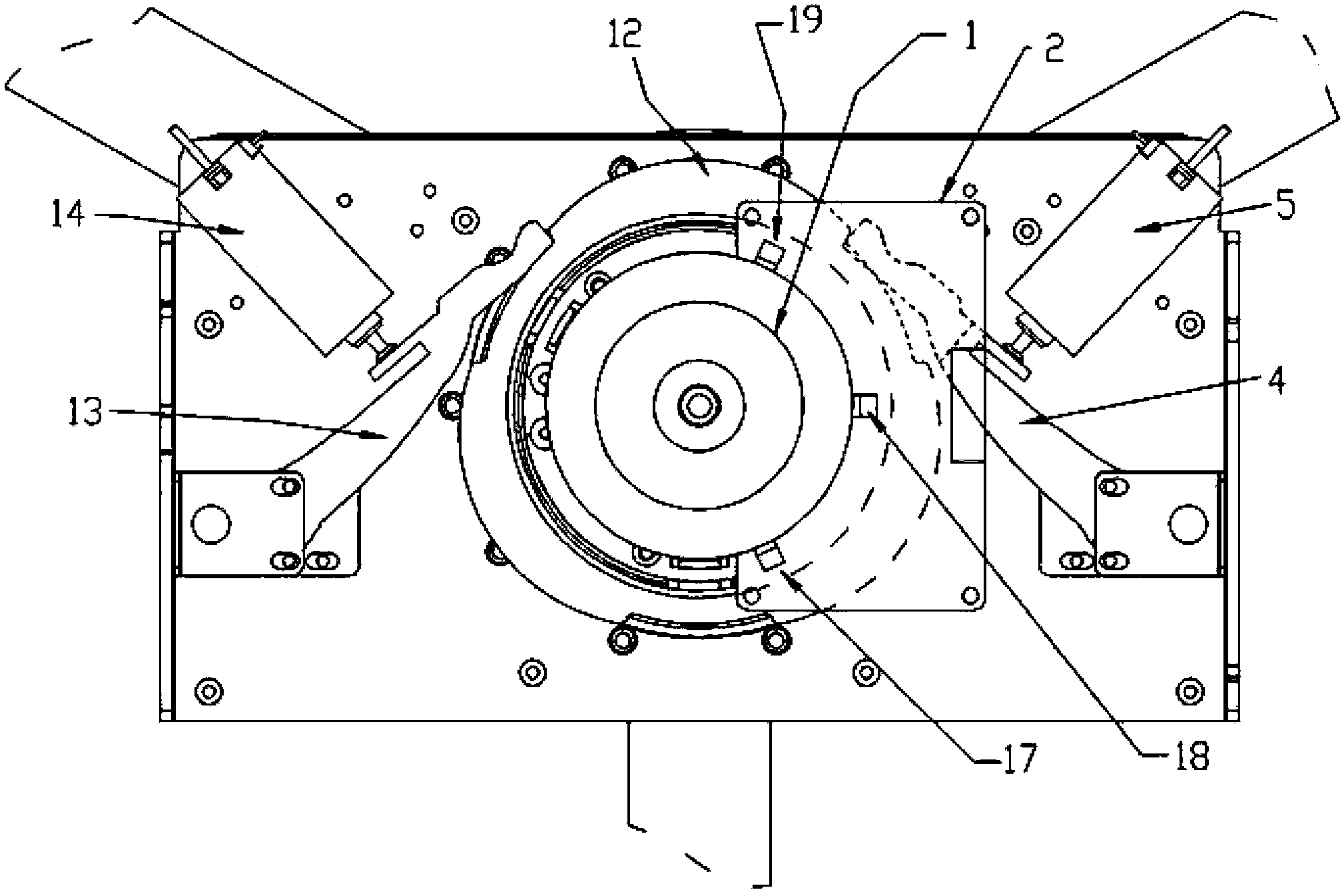
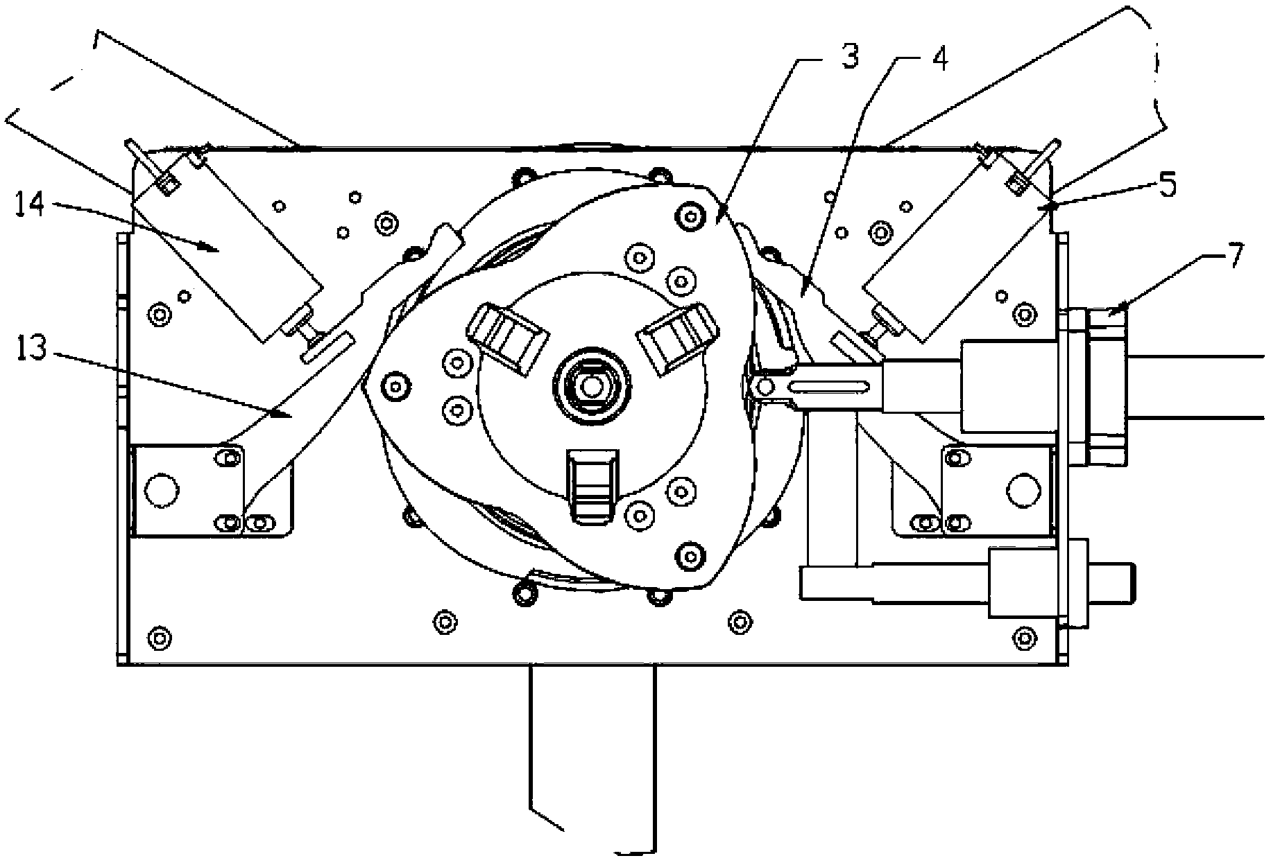
[0038] refer to Figure 1~5As shown, the embodiment of the present invention provides a three-roller gate movement, including a movement casing, a main shaft 8 placed in the movement casing, a main shaft bearing 6, a main shaft locking device, a main movement beam 11, the The end of the main shaft 8 is connected to the third stop roller, the other end of the main shaft 8 is connected to the main shaft locking device, the main shaft bearing 6 is sleeved on the outer edge of the main shaft 8, and the movement beam 11 has a The outer wall of the main shaft bearing 6 is perpendicular to the movement g...


PUM


Abstract

The invention provides a three-roller gate movement. The three-roller gate movement comprises a movement shell, and a main shaft, a main shaft bearing, a main shaft locking device and a movement girder which are arranged inside the movement shell, wherein the tail end of the main shaft is connected with a three baffle rollers, and the other end of the main shaft is connected with the main shaft locking device; the main shaft bearing is sleeved on the outer edge of the main shaft in a connecting manner; the movement girder is provided with a through hole capable of penetrating through the main shaft; the outer wall of the main shaft bearing is vertical to the movement grinder, and is sleeved in the through hole in the movement grinder; the edge of the through hole is fixedly connected with the outer wall of the main shaft bearing; the periphery of the through hole in the movement grinder is provided with a bolt hole; and the movement grinder is fixedly connected with the movement shell through bolts or rivets by penetrating through the bolt hole. When the equipment is impacted during using process, an angle inside the main shaft is deflected along with the impact deformation, but the axle is not twisted.

Description

technical field [0001] The invention belongs to the field of channel management and control equipment, and in particular relates to a three-bar roller gate device for controlling the entrance and exit of personnel. Background technique [0002] The main shaft of the existing semi-automatic three-roller gate movement needs to be leveled with the three-roller gate shell during the installation process, and its various components are not completely fixed on the main shaft, and the angle adjustment is required, that is, the main shaft bearing is installed. When encountering brute force passing or violent impact on the retaining roller, it is particularly easy to cause the retaining roller stand or the main shaft and internal parts to be deformed and unable to rotate on one axis, causing the machine to stop working. [0003] In addition, the existing semi-automatic three-roller gate movement also has the following deficiencies: [0004] The volume is large, and the thickness of ...

Claims


Application Information

Patent Timeline
Patent Type & Authority Applications(China)
IPC IPC(8): E06B11/08
CPCE06B11/08
Inventor 车全宏郭诗迈张宏根姚乘飞曾科明
Owner DONGGUAN ZKTECO ELECTRONICS TECH
Why Eureka
Try Eureka