Centrifugal pump with impeller rotation boosting structure

A power-assisted structure and impeller rotation technology, which is applied to the components, pumps, pump elements, etc. of the pumping device used for elastic fluid, can solve the problem that energy is not effectively used, and achieve the effect of reducing torque output

Active Publication Date: 2013-10-23
上海瑞晨环保科技股份有限公司
View PDF6 Cites 45 Cited by
  • Summary
  • Abstract
  • Description
  • Claims
  • Application Information

AI Technical Summary

Problems solved by technology

The low-pressure fluid in the sealing ring flows back to the inlet of the impeller through the balance hole. In this way, the axial force on the front and rear cover plates of the impeller is kept in balance. There is a large pressure difference, but this part of the energy has not been effectively used, and cannot help the rotation of the impeller

Method used


Image

  • Centrifugal pump with impeller rotation boosting structure
  • Centrifugal pump with impeller rotation boosting structure
  • Centrifugal pump with impeller rotation boosting structure

Examples


Embodiment Construction

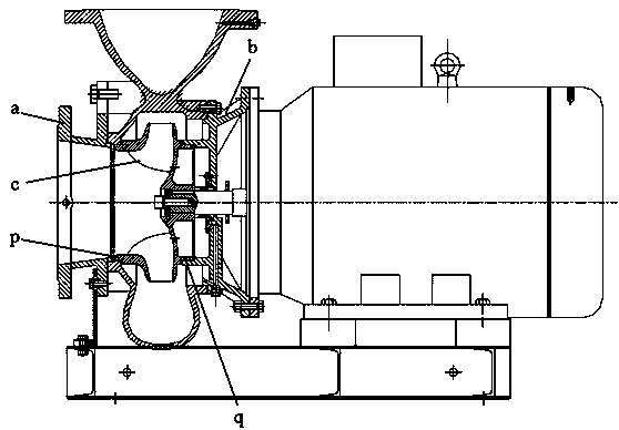
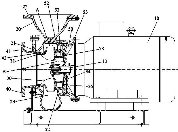
[0019] see Figure 2 to Figure 5 As shown, the present invention provides a centrifugal pump 100, including a motor 10, a pump body 20 located at one end of the motor 10 and connected to the motor 10, an impeller 30 located in the pump body 20, a front end cover 40 and a rear cover located on the front and rear sides of the impeller 30. End cap 50.

[0020] see figure 2 As shown, the pump body 20 includes a front port 21 and an upper port 22, which are respectively located at the front end and the upper end of the impeller 30, for providing an input and output path for fluid. The pump body 20 is provided with an accommodating cavity 23 for accommodating the impeller 30 . The front port 21 of the pump body 20 is mated with the front end cover 40 .

[0021] The impeller 30 is located in the accommodating chamber 23 of the pump body 20 and below the upper port 22. The center of the impeller 30 is connected with the rotating shaft 11 of the motor 10 and can follow the directio...


PUM


Abstract

The invention provides a centrifugal pump with an impeller rotation boosting structure, the centrifugal pump comprises a motor, a pump body, an impeller, and a front end cover and a rear end cover at the front and rear sides of the impeller, the impeller is provided with a rear seal ring, the rear end cover is provided with a seal baffle ring which extends toward the impeller and covers at the periphery of the rear seal ring, a seal cavity is formed between the seal baffle ring of the rear end cover and the rear seal ring of the impeller, and the rear seal ring is provided with a plurality of slip sheets capable of slipping into the seal cavity. Compared with the prior art, through adopting the improved design of the end cover and the impeller of the centrifugal pump and utilizing the improved structures (such as the seal cavity and the slip sheets) between the seal baffle ring and the rear seal ring, pressure difference between a high pressure area and a low pressure area at two ends of the seal cavity is converted into power for pushing the impeller to rotate during the rotation of the impeller, so that the torque output of the motor is reduced.

Description

technical field [0001] The invention relates to the technical field of centrifugal pumps, in particular to a centrifugal pump with an impeller rotation assist structure. Background technique [0002] When the traditional centrifugal pump is running, the impeller rotates at high speed in the pump casing. When the pressure areas of the front and rear cover plates of the impeller are different, an axial force will be generated. If the axial force is too large, the motor bearing will heat up. In general, the force bearing area of ​​the impeller front cover a is smaller than the force bearing area of ​​the impeller rear cover b, please refer to figure 1 As shown, this will generate an axial force pointing to the inlet of the impeller c. In order to reduce the imbalance of the axial force, an impeller rear orifice ring q is generally made on the back of the impeller. The diameter of the rear orifice ring q is the same as the diameter of the impeller front orifice ring p , so that...

Claims


Application Information

Patent Timeline
Patent Type & Authority Applications(China)
IPC IPC(8): F04D29/00F04D29/08F04D29/42
Inventor 王野陈万东陈招锋
Owner 上海瑞晨环保科技股份有限公司
Why Eureka
Try Eureka