Hybrid vehicle and control method therefor

a hybrid vehicle and control method technology, applied in the field of hybrid vehicles, can solve the problems of drag torque (mechanical loss), drag torque (mechanical loss), and drag torque (mechanical loss) generated in the first motor, and achieve the effect of reducing the torque (driving torque) of the driving shaft, reducing the drag torque, and reducing the regeneration torque and drag torque in the first motor

Inactive Publication Date: 2018-09-20
TOYOTA JIDOSHA KK
View PDF0 Cites 2 Cited by
  • Summary
  • Abstract
  • Description
  • Claims
  • Application Information

AI Technical Summary

Benefits of technology

[0012]According to the control method for the hybrid vehicle as described in the foregoing, the hybrid vehicle can travel with the driving torque of the driving shaft based on regeneration torque and drag torque in the first motor, when the counter-electromotive voltage of the first motor is made higher than the direct current-side voltage of the first inverter. When the second motor rotates, drag torque (mechanical loss) is generated in the second motor. When the counter-electromotive voltage of the second motor is higher than the direct current-side voltage of the second inverter, regeneration torque based on the counter-electromotive voltage is also generated in addition to the drag torque in the second motor. The generated torque is output to the driving shaft as braking torque. The engine and the step up-down converter are controlled such that the rotational speed of the first motor becomes smaller and the voltage of the high voltage-side electric power line becomes lower when the accelerator is off than when the accelerator is on during the specified traveling. When the rotational speed of the first motor is made smaller, the regeneration torque and the drag torque in the first motor can be made smaller. As a result, the torque (driving torque) of the driving shaft based on the regeneration torque and the drag torque can be reduced. When the voltage of the high voltage-side electric power line is made lower, the regeneration torque can be generated and increased in the second motor, while the torque of the driving shaft can be reduced (can be increased as braking torque). As a result, as compared with the case where the rotational speed of the first motor is simply reduced, the total torque of the driving shaft can sufficiently be reduced (can be increased as braking torque). As a result, a sufficient braking force of the hybrid vehicle can be secured.

Problems solved by technology

An issue of the hybrid vehicle is how to cause driving torque of the output member, when the accelerator is off while the hybrid vehicle travels with the gates of the inverters being cut off and the engine being operated, to be sufficiently lower than the driving torque when the accelerator is on.
When the first motor rotates, drag torque (mechanical loss) is generated in the first motor.
When the second motor rotates, drag torque (mechanical loss) is generated in the second motor.

Method used


Image

  • Hybrid vehicle and control method therefor
  • Hybrid vehicle and control method therefor
  • Hybrid vehicle and control method therefor

Examples


Embodiment Construction

[0021]Now, modes for carrying out the present disclosure will be described in detail based on embodiments.

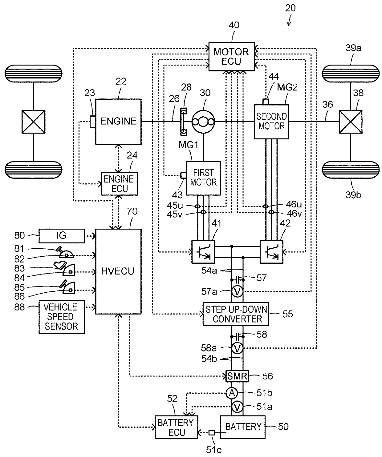
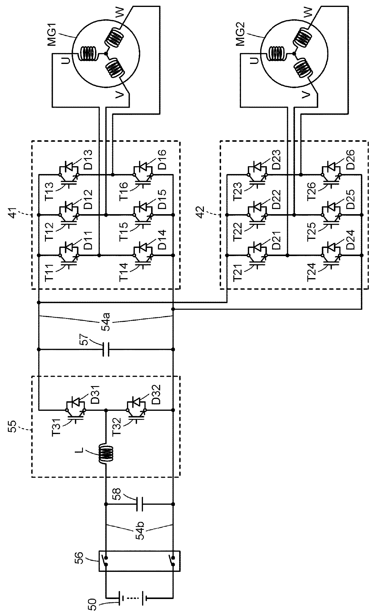
[0022]FIG. 1 is a block diagram illustrating an outlined configuration of a hybrid vehicle 20 as one embodiment of the present disclosure. FIG. 2 is a block diagram illustrating an outlined configuration of an electric drive system including a first motor MG1 and a second motor MG2. As illustrated in the drawings, the hybrid vehicle 20 of the embodiment includes an engine 22, a planetary gear set 30, a first motor MG1, a second motor MG2, a first inverter 41, a second inverter 42, a step up-down converter 55, a battery 50 as an electric storage device, a system main relay (also abbreviated to “SMR”) 56, and a hybrid electronic control unit (referred to as “HVECU” below) 70.

[0023]The engine 22 is configured as an internal combustion engine that outputs motive power by using fuel such as gasoline, and gas oil. The operation of the engine 22 is controlled by an engine electronic co...


PUM


Abstract

An engine and a step up-down converter are controlled such that a counter-electromotive voltage of a first motor becomes higher than direct current-side voltages of a first inverter and a second inverter and thereby torque for forward travel is output from the first motor to a driving shaft through a planetary gear set, when an accelerator is on during specified travelling with gates of the first inverter and the second inverter being cut off and the engine being operated. The engine and the step up-down converter are controlled such that the rotational speed of the first motor becomes smaller and the voltage of the high voltage-side electric power line becomes lower when the accelerator is off than when the accelerator is on during the specified traveling.

Description

CROSS-REFERENCE TO RELATED APPLICATIONS[0001]The disclosure of Japanese Patent Application No. 2017-052606 filed on Mar. 17, 2017 including the specification, drawings and abstract is incorporated herein by reference in its entirety.BACKGROUND1. Technical Field[0002]The present disclosure relates to a hybrid vehicle and a control method therefor.2. Description of Related Art[0003]As a hybrid vehicle of this type, there has been proposed a vehicle including an engine, a first motor, and a planetary gear mechanism including a carrier, a sun gear, and a ring gear that are connected to the engine, the first motor, and an output member coupled with driving wheels. The hybrid vehicle also includes a second motor connected to the output member, an inverter that drives the first motor and the second motor, and a battery connected to the inverter through an electric power line (see, for example, Japanese Patent Application Publication No. 2013-203116). When an accelerator is on while the hyb...

Claims


Application Information

Patent Timeline
Patent Type & Authority Applications(United States)
IPC IPC(8): B60L11/14B60L15/00B60L3/00B60K6/445B60W10/06B60W10/08B60W20/15B60L50/16
CPCB60L11/14B60L15/007B60L3/0046B60K6/445B60L3/003B60W10/06B60W10/08B60W20/15B60L2240/423B60L2220/14B60L2240/549B60L2240/547B60L2210/42B60K6/365B60W10/30B60W20/14B60L7/14B60W2510/081B60W2520/10B60W2710/0644B60L50/16Y02T10/62Y02T10/64Y02T10/7072Y02T10/72
Inventor TAKAYAMA, DAIKI
Owner TOYOTA JIDOSHA KK
Why Eureka
Try Eureka