

Regenerating braking system including synchronous motor with field excitation and control method thereof
- Summary
- Abstract
- Description
- Claims
- Application Information
AI Technical Summary
Benefits of technology
Problems solved by technology
Method used
Image

Examples
first embodiment
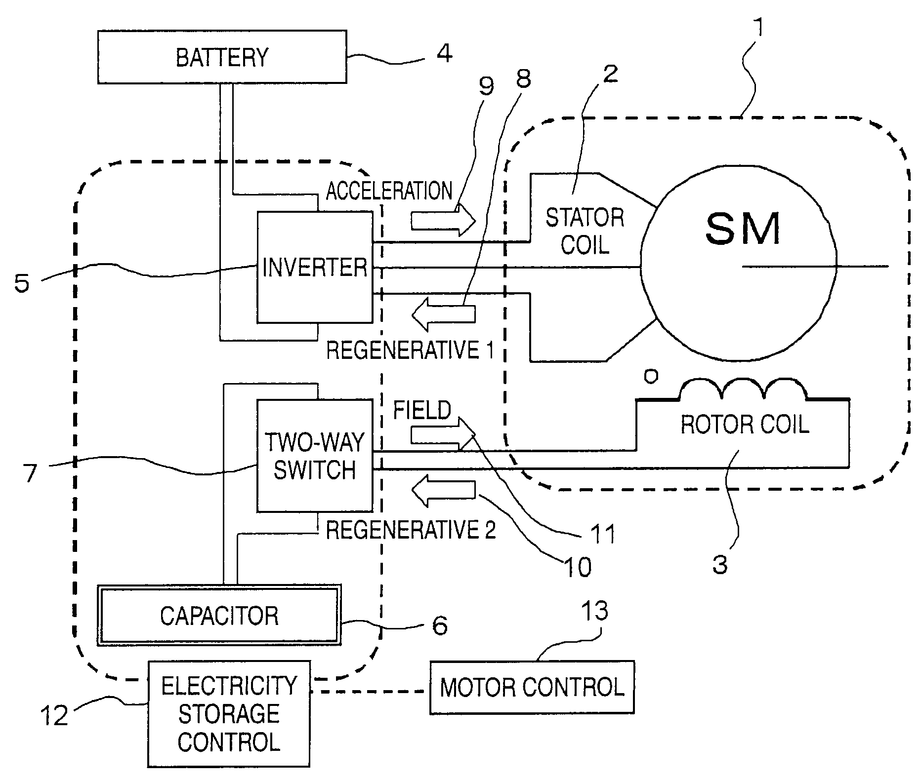
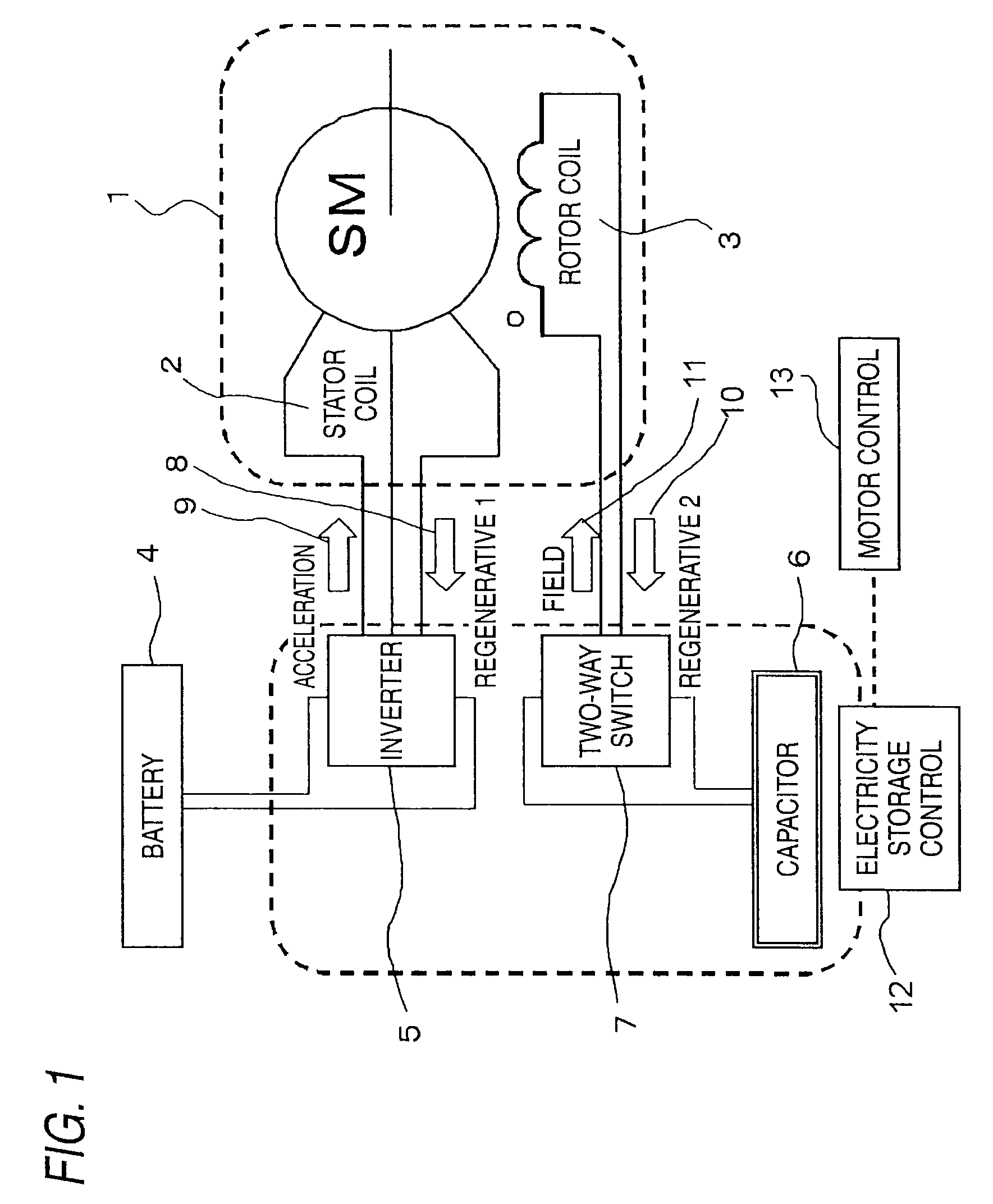
[0032]FIG. 1 is a block diagram of a regenerating braking system including a synchronous motor with field coil excitation according to a first embodiment to carry out the invention. In FIG. 1, a synchronous motor with field coil excitation 1 has a rotor coil 3 provided in a cylindrical stator coil 2. An inverter 5 is connected to the stator coil 2 so as to transfer acceleration power and regenerative power. Further, a battery 4 is connected to the inverter 5. On the other hand, a two-way switch 7 is connected to the rotor coil 3 so as to transfer field power and regenerative power. Further, a capacitor 6 is connected to the two-way switch 7. As control means for controlling transfer of power, etc., an electricity storage controller 12 is connected to the inverter 5, the two-way switch 7, and the capacitor 6. A motor controller 13 is connected to the electricity storage controller 12.
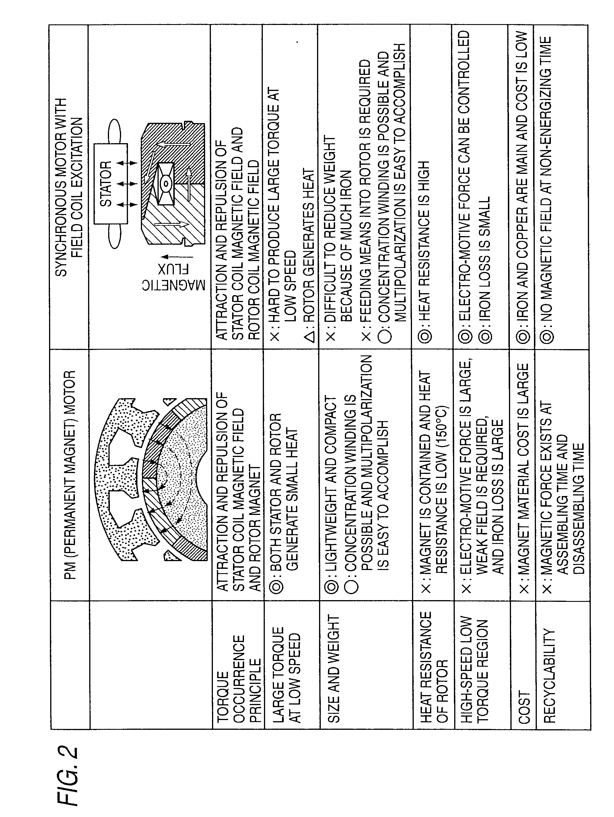
[0033]FIG. 2 is a characteristic drawing to make a comparison between the features of a permanent mag...
second embodiment
[0054]FIGS. 9 and 10 are schematic representations of a regenerating braking system including a synchronous motor with field excitation according to a second embodiment to carry out the invention. The regenerating braking system according to the second embodiment further has a two-way DC / DC converter 19 between an inverter 5 and a capacitor 6 in addition to the configuration of the first embodiment. The arrows in the figures indicate the directions of regenerative braking current and field current and input / output of electric power as in the first embodiment.
[0055]In the above-described regenerating braking system, when a motor is decelerated, control is performed so as to store a part of steep regenerative power in a second electricity storage device through the inverter and the two-way DC / DC converter 19. When the motor is accelerated, control is performed so as to supply acceleration power to a stator coil through the two-way DC / DC converter 19 and the inverter.
[0056]FIG. 9 shows...
third embodiment
[0060]FIGS. 11 and 12 are schematic representations of a regenerating braking system including a synchronous motor with field excitation according to a third embodiment to carry out the invention. The regenerating braking system according to the third embodiment has a similar configuration to that of the second embodiment, but they differ in control method.
[0061]In the third embodiment, control is performed so as to transfer electric power from a battery to a capacitor through a two-way DC / DC converter if charge of the capacitor is insufficient (FIG. 11) regardless of whether a motor is accelerated or decelerated. Conversely, if charge of the capacitor is excessive (FIG. 12), control is performed so as to transfer electric power from the capacitor to the battery through the two-way DC / DC converter. Electric power can be transferred between the capacitor and the battery through the two-way DC / DC converter not through an inverter although the circuitry is connected to the inverter.
[00...
PUM
 Abstract
Description
Claims
Application Information