Electronic device-mounted apparatus and noise suppression method for same

Inactive Publication Date: 2010-04-15
NEC CORP +1
View PDF38 Cites 5 Cited by
  • Summary
  • Abstract
  • Description
  • Claims
  • Application Information

AI Technical Summary

Benefits of technology

[0017]It is an object of the present invention to provide an electronic device-mounted apparatus and a noise suppression method that can solve at least one of the above-described problems. An example of this object is to effectively cause

Problems solved by technology

However, the flow of a portion of the noise current that flows through radiator plate 5 shown above to surfaces other than the printed board 1 side of radiator plate 5 raises the concern that noise will be superposed upon devices that are packaged by this electronic de

Method used


Image

  • Electronic device-mounted apparatus and noise suppression method for same
  • Electronic device-mounted apparatus and noise suppression method for same
  • Electronic device-mounted apparatus and noise suppression method for same

Examples


first embodiment

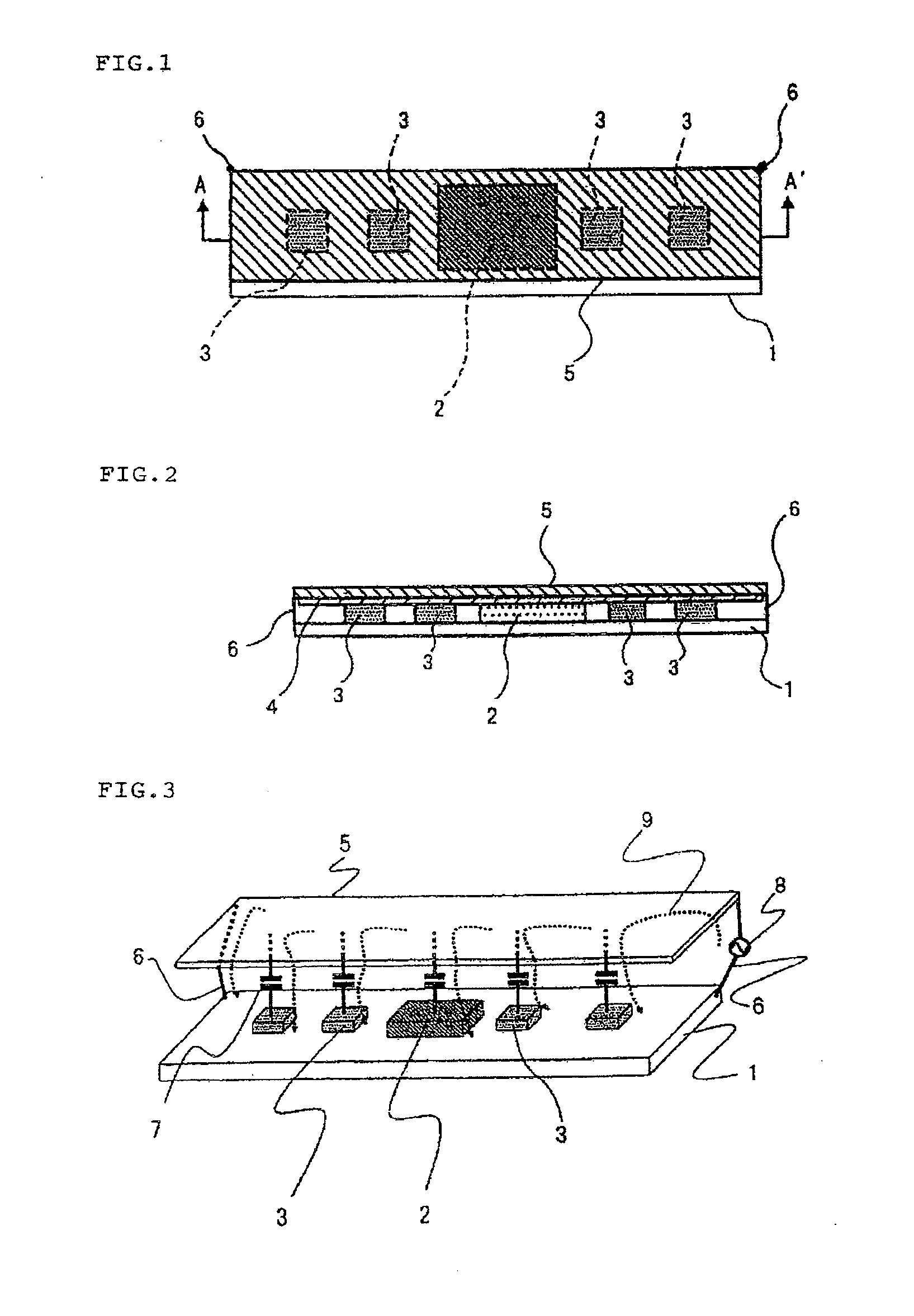
[0040]FIG. 5 is a top view of the electronic device-mounted apparatus that relates to the first embodiment of the present invention, and FIG. 6 is a sectional view taken along line A-A′ of FIG. 5. As shown in FIG. 5 and FIG. 6, electronic devices 2 and 3 that operate by a clock signal are mounted on printed board 1. In the present example, electronic devices 2 and 3 have mutually different planar shapes. Although no particular limitations apply, the shapes of electronic devices 2 and 3 are, for example, semiconductor finished-products such as System-in-Package (SiP) in which one or a plurality of LSI bare chips are mounted on a package substrate with an interposer substrate interposed and which are sealed by an insulating material.

[0041]Heat-conductive sheet 4 and radiator plate 5 are stacked in that sequence over electronic devices 2 and 3 and thus rest on electronic devices 2 and 3. In other words, electronic devices 2 and 3 are interposed between printed board 1 and radiator plat...

second embodiment

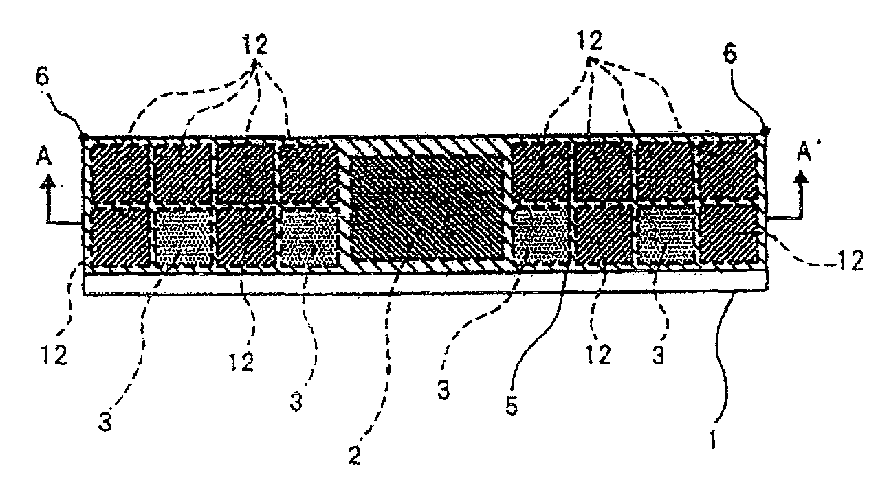
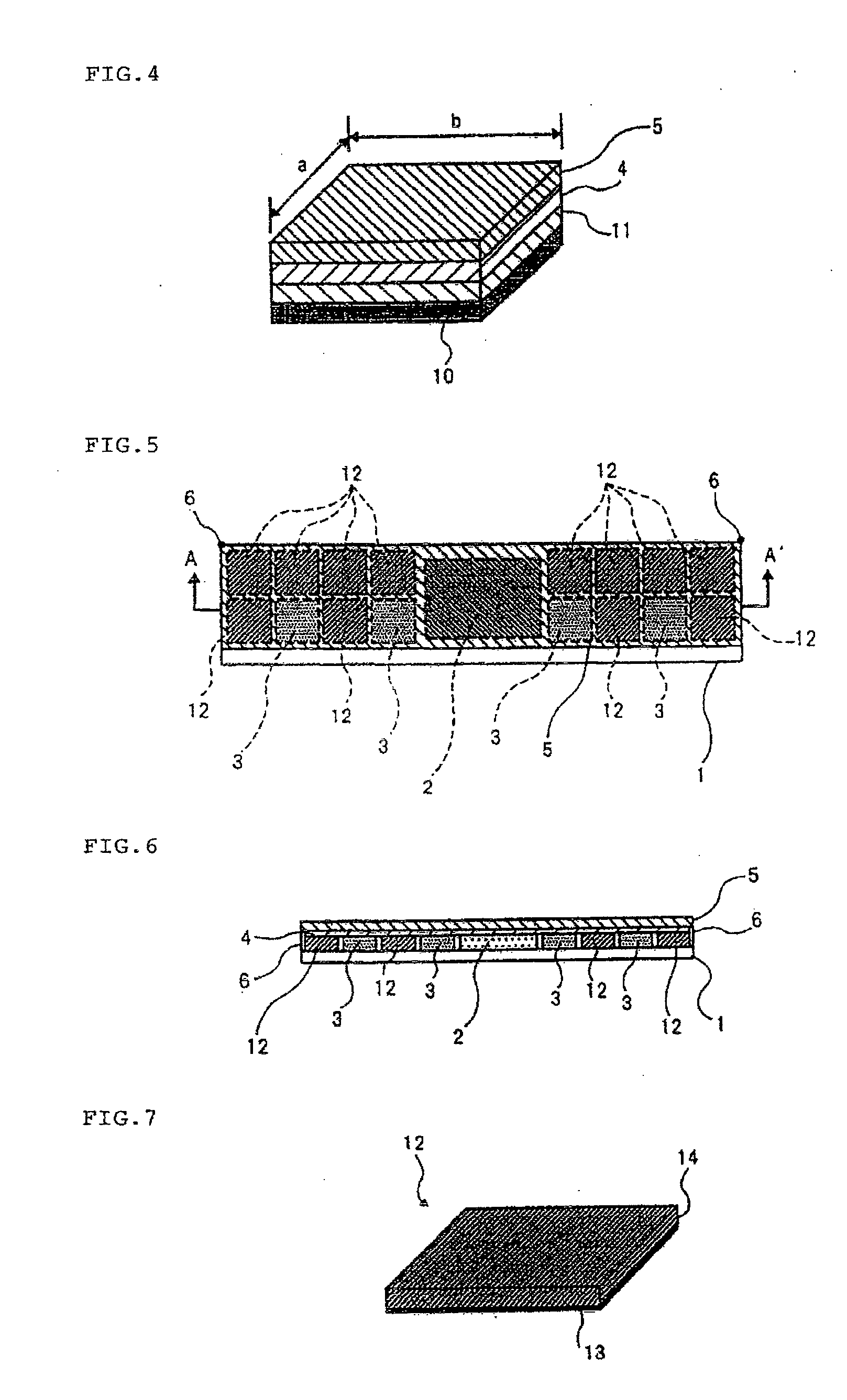
[0061]FIG. 13 is a top view of the electronic device-mounted apparatus that relates to the second embodiment of the present invention, and FIG. 14 is a sectional view taken along line A-A′ of FIG. 13.

[0062]As shown by FIGS. 13 and 14, electronic devices 2 and 3 are mounted on printed board 1, and radiator plate 5 is installed on electronic devices 2 and 3 with heat-conduction sheet 4 interposed. Still further, radiator plate 5 and the ground of printed board 1 are electrically connected by ground connection lines 6 at both ends in the longitudinal direction of printed board 1. A plurality of dielectric components 12 are arranged at a plurality of locations, that are isolated from the sites where electronic devices 2 and 3 are mounted, between radiator plate 5 and printed board 1 to electrically connect radiator plate 5 and the ground of printed board 1. Dielectric component 12 has substantially the same shape as the planar shape of electronic device 3. In addition, capacitors are fo...

third embodiment

[0066]FIG. 15 is a top view of the electronic device-mounted apparatus that relates to the third embodiment of the present invention, and FIG. 16 is a sectional view taken along line A-A′ of FIG. 15. Because the form shown in these figures is a modification of the second embodiment, only points of difference will be described.

[0067]In the present embodiment, one dielectric component 12 is interposed between printed board 1 and radiator plate 5 in an area having a length that is at least one-third of radiator plate longitudinal dimension L from the end of radiator plate 5 to which ground connection line 6 is connected. This dielectric component 12 is composed of a frame shape that encloses electronic device 3 on printed board 1 with spacing interposed, as shown in by the dotted lines in FIG. 15.

[0068]In this embodiment as well, nearly all of the noise current that flows to radiator plate 5 from ground connection line 6 that is a noise source can be actively returned to the ground of ...


PUM


Abstract

A noise electric current flowing through a heat sink is efficiently discharged to the ground of a printed circuit board to reduce levels of clock signal harmonic noises generated from the heat sink. An electronic device-installed apparatus is provided with a printed circuit board (1), one or more of electronic devices (2, 3) that are mounted on the printed circuit board (1) and that operate in accordance with a clock signal, and a heat sink means set to hold the electronic devices (2, 3) together with the printed circuit board (1). The heat sink means (5) is connected with the ground of the printed circuit board (1) through a connecting unit (6) and a plurality of dielectric components (12), which are independent of the electronic devices (2, 3), are provided between portions of the printed circuit board except those on which the electronic devices (2, 3) are mounted and the heat sink means (5).

Description

TECHNICAL FIELD[0001]The present invention relates to an electronic device-mounted apparatus. In particular, the present invention relates to an electronic device-mounted apparatus that is provided with electronic devices such as LSI that operate according to a clock signal, and a heat radiator provided on the electronic devices for dispersing heat that is generated by the operating current of the electronic devices. The present invention further relates to a noise suppression method for avoiding the propagation of clock signal harmonic noise in the heat radiator and the radiation of noise from the heat radiator.BACKGROUND ART[0002]An electronic device such as LSI that is composed of a single chip, that carries out the functions of main memory, control, and arithmetic operations, and that is used in an information processing apparatus such as a personal computer or work station requires large current in order to realize high-speed processing capabilities. A heat radiator means was i...

Claims


Application Information

Patent Timeline
IPC IPC(8): H05K7/20
CPCH05K1/0203H05K1/0216H05K1/0231H05K2201/1056H05K1/162H05K2201/10204H05K1/0243
Inventor IMAZATO, MASAHARUONO, MASAYASUYAMAZAKI, NAOTO
Owner NEC CORP
Why Eureka
Try Eureka