Practical steam engine

a steam engine and steam technology, applied in the direction of machines/engines, oscillatory slide valves, mechanical equipment, etc., can solve the problems of low density, low heating value solids, liquids and gaseous substances, and low cost of high-grade commercial fuels, and achieve low torque output, high speed, and add value to the process of wood products

Inactive Publication Date: 2016-08-11
MICROSTEAM
View PDF9 Cites 3 Cited by
  • Summary
  • Abstract
  • Description
  • Claims
  • Application Information

AI Technical Summary

Benefits of technology

[0008]The present invention is directed to a Practical Steam Engine that can run at higher speeds (at least 400 rpms) and, thus, requires lower torque outputs. This lower torque output, in turn, allows the power delivery through smaller components that do not need to be supported by a massive concrete foundation as does the prior art uniflow engine. The fact that the Practical Steam Engine can be made compactly and relatively portable makes it ideal for off-grid power generation applications. The Practical Steam Engine may be fueled by biomass, such as slash and thinnings as part of forest management practices, or for providing steam-generated power at a merchantable timber source to add value to wood product processes.

Problems solved by technology

Low grade fuels (low density, low heating value solid, liquid and gaseous substances) are not competitive with higher grade commercial fuels in small scale (e.g., less than 2000 kW) mobile and stationary power plants.
This is mainly due to the lack of small scale, efficient, low cost steam prime movers that can economically convert low grade fuels into usable, industrial power.
The traditional reciprocating steam engine, in its various forms, has become economically and technologically obsolete due to the availability of refined, petroleum based fuels that were better utilized in more efficient heat engine cycles (Otto, Diesel and Brayton cycles) and the development of low cost electrical power delivered by the interconnected utility power grid.
The traditional steam engine is limited by its ability to convert raw, unrefined fuel sources into clean, high quality steam energy that is converted to mechanical work.
But it could only work at relatively low speeds (e.g., generally not exceeding 400 rpm).
Thus, it required high torque outputs.
The result is that the Skinner Uniflow engine had five major weaknesses: (a) massive and costly components that could not withstand high reaction forces generated by large piston diameters due to low rotational speeds (generally not above 400 rpm); (b) double acting pistons required complex piston rod / crosshead / connecting rod assemblies that limited rotational speeds due to high inertia forces that could not be adequately balanced at high speed; (c) long cutoffs of up to 40% that adversely impacted thermodynamic performance; (d) need for large concrete foundations to support the heavy engine weights and separate condenser, and, therefore, lack of portability; and (e) higher cost compared to less efficient steam turbines due to higher manufacturing and labor costs.

Method used


Image

  • Practical steam engine
  • Practical steam engine
  • Practical steam engine

Examples


Embodiment Construction

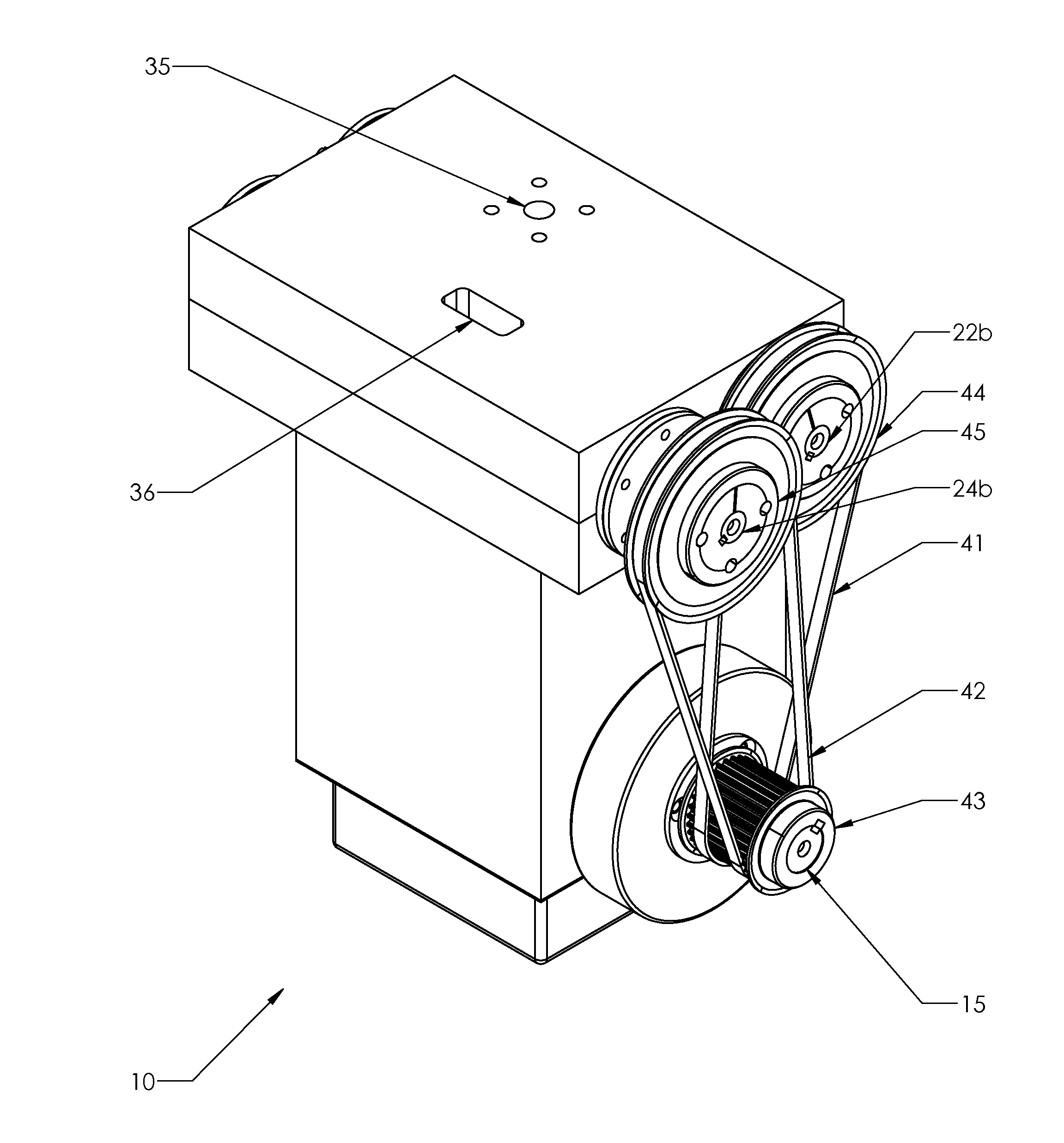
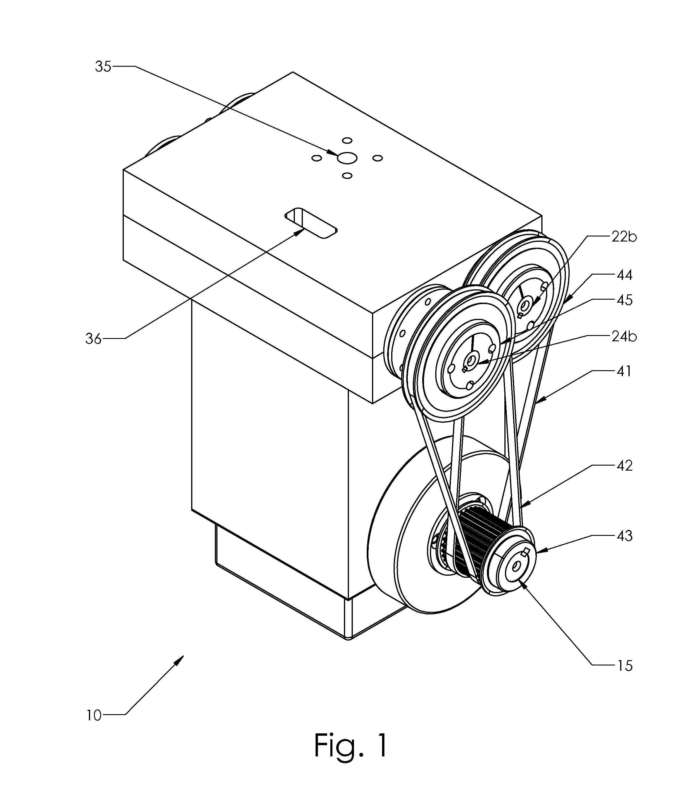
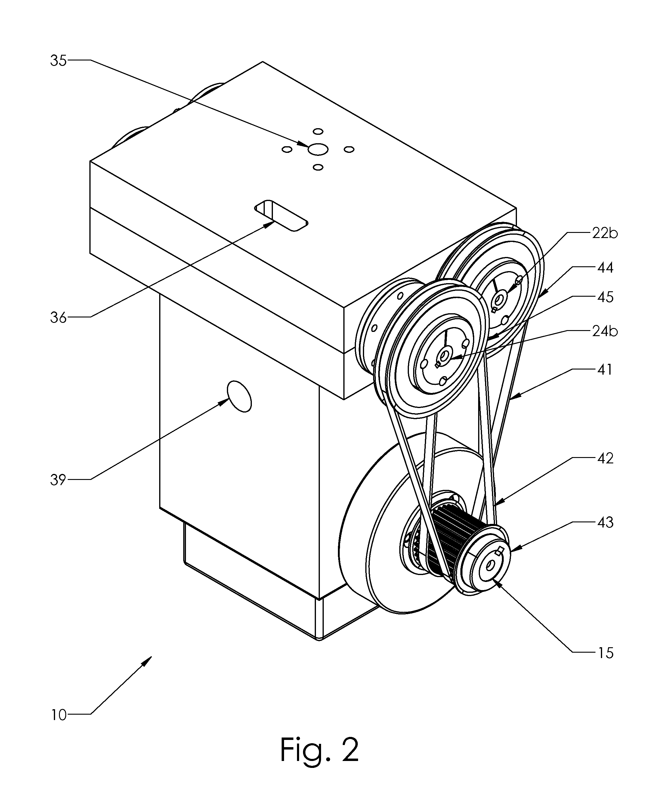
[0031]The present invention is described more fully hereinafter with reference to the accompanying drawings, in which preferred embodiments of the invention are shown. This invention may, however, may be embodied in many different forms and should not be construed as limited to the embodiments set for herein; rather, these embodiments are provided so that this disclosure will be thorough and complete and will fully convey the scope of the invention to those skilled in the art. The current invention is a high speed, two-stroke engine that is counter flow, semi-uniflow, or uniflow and is comprised of at least one variable rotary valve mechanism. Working fluid, referred to herein, may be organic and / or inorganic fluid, naturally occurring and / or man-made. Working fluid may include: Chlorofluorocarbon (CFC) (e.g. R-11, R-12); Hydro-fluorocarbons (HFC) (e.g. R-134a, R-245fa); Hydro-chlorofluorocarbon (HCFC) (e.g. R-22, R-123); Hydrocarbons (HC) (e.g. Butane, methane, pentane, propane, et...


PUM


Abstract

The current invention is a high speed, two-stroke engine that is counter flow, semi-uniflow, or uniflow and is comprised of at least one variable rotary valve mechanism.

Description

CROSS-REFERENCES TO RELATED APPLICATIONS[0001]Not ApplicableSTATEMENT REGARDING FEDERALLY SPONSORED RESEARCH OR DEVELOPMENT[0002]Not ApplicableINCORPORATION-BY-REFERENCE OF MATERIAL SUBMITTED ON A COMPACT DISC[0003]Not ApplicableBACKGROUND OF INVENTION[0004]Low grade fuels (low density, low heating value solid, liquid and gaseous substances) are not competitive with higher grade commercial fuels in small scale (e.g., less than 2000 kW) mobile and stationary power plants. This is mainly due to the lack of small scale, efficient, low cost steam prime movers that can economically convert low grade fuels into usable, industrial power.[0005]The traditional reciprocating steam engine, in its various forms, has become economically and technologically obsolete due to the availability of refined, petroleum based fuels that were better utilized in more efficient heat engine cycles (Otto, Diesel and Brayton cycles) and the development of low cost electrical power delivered by the interconnecte...

Claims


Application Information

Patent Timeline
Patent Type & Authority Applications(United States)
IPC IPC(8): F01K7/00F01L7/12
CPCF01L7/12F01K7/00F01B17/04
Inventor TOLBERT, JOSHUA A.TOLBERT, BENJAMIN J.
Owner MICROSTEAM
Why Eureka
Try Eureka