
Diaphragm valve body of flow control valve

A technology of flow regulating valve and diaphragm valve, applied in the direction of diaphragm valve, diaphragm, valve device, etc., can solve the problem of unstable flow regulation and so on

Inactive Publication Date: 2013-10-23
LIXIL CORP
View PDF2 Cites 14 Cited by
  • Summary
  • Abstract
  • Description
  • Claims
  • Application Information

AI Technical Summary

Problems solved by technology

[0024] The present invention is based on the above circumstances, and an object of the present invention is to provide a flow regulator that solves the problem that the flow regulation becomes unstable due to the valve plate part of the diaphragm being separated from the retainer and vibrates, so that the flow regulation can be performed stably. Diaphragm body of the valve

Method used


Image

  • Diaphragm valve body of flow control valve
  • Diaphragm valve body of flow control valve
  • Diaphragm valve body of flow control valve

Examples


Embodiment Construction

[0074] Next, embodiments of the present invention will be described in detail with reference to the drawings.

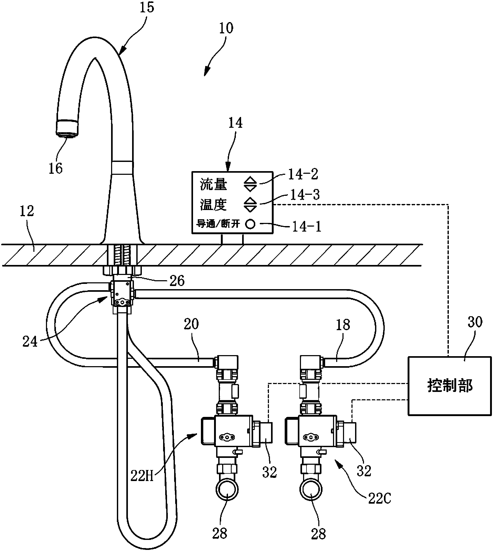
[0075] exist figure 1 Among them, 10 is a faucet, which has an operation part 14 arranged on the counter 12 and a water outlet pipe 15 standing up from the counter 12 .

[0076] The water outlet pipe 15 has a gooseneck shape and has a water outlet 16 at the end.

[0077] In addition, the operation part 14 is provided with: the water discharge and water stop operation part 14-1 for implementing the water discharge from the water outlet 16 and the water stop, the flow adjustment operation part 14-2 for adjusting the flow of the water discharge, and the water discharge control part 14-2. The temperature adjustment operating part 14-3 etc. for adjusting the temperature.

[0078] Below the counter 12 , flow control valves 22C and 22H according to the present embodiment are provided on the cold water supply passage 18 and the hot water supply passage 20 , respectively. ...


PUM


Abstract

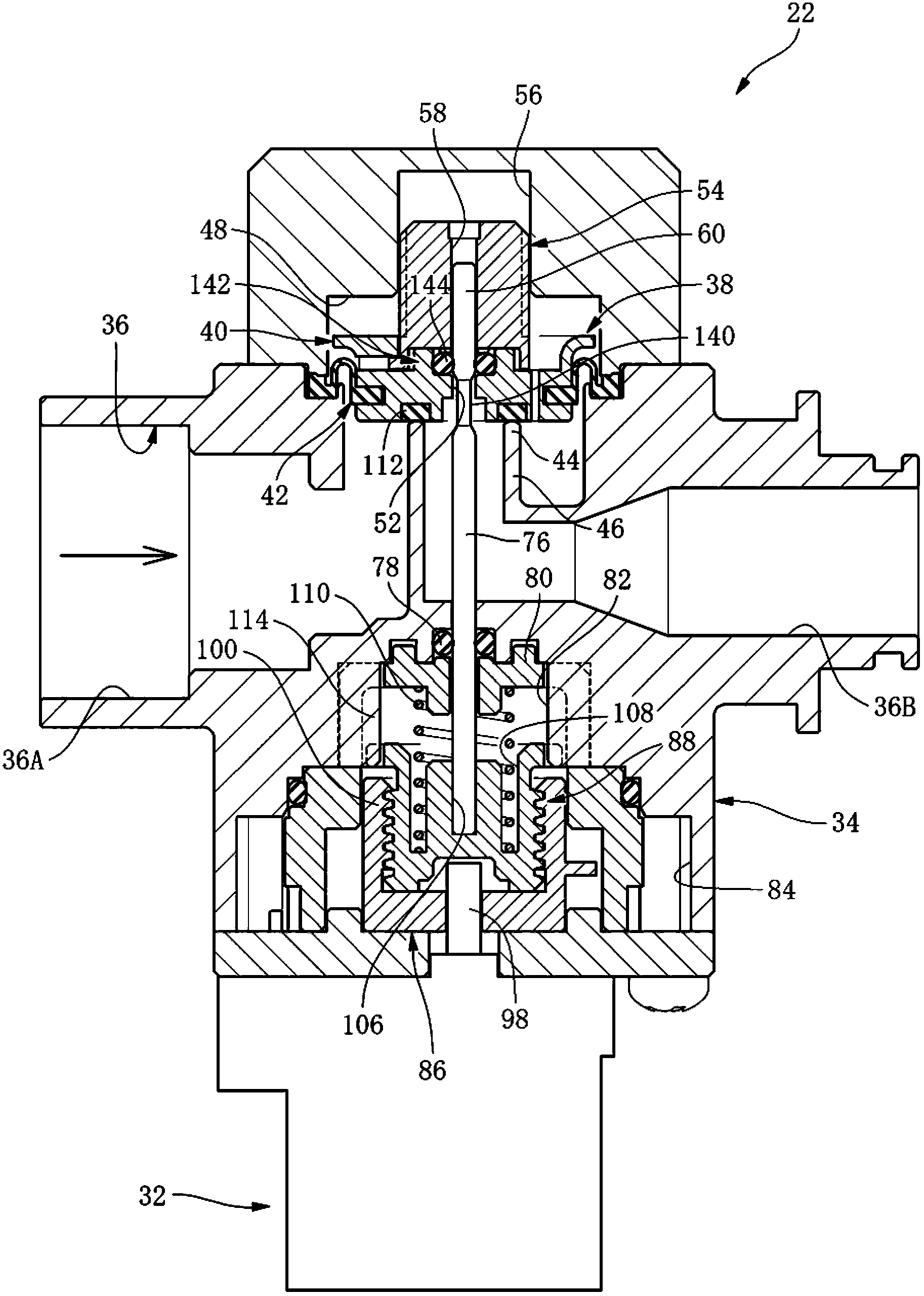
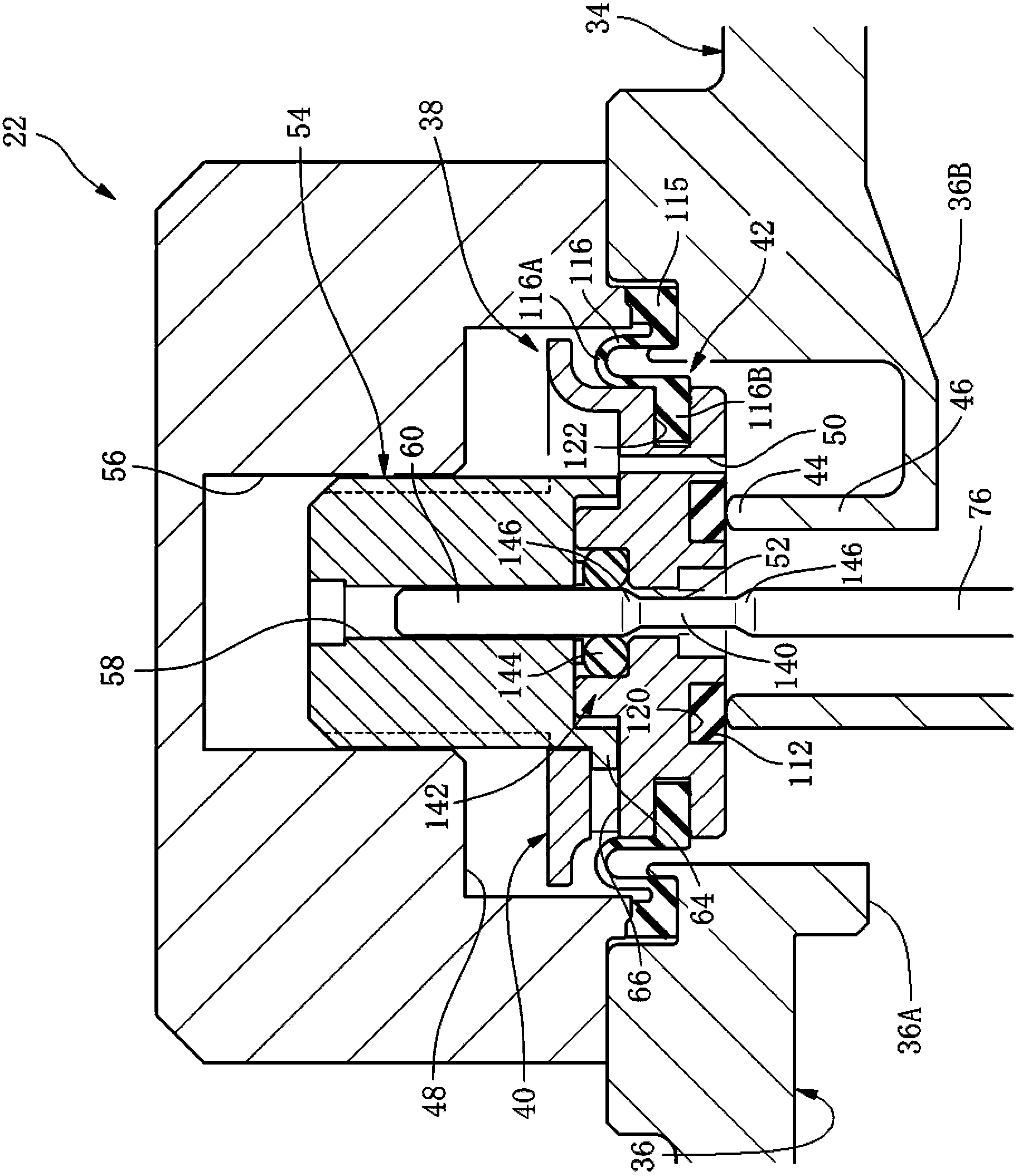
The invention provides a diaphragm valve body of a flow control valve, and solves the problem of unstable flow regulation caused by vibration and separation of a valve plate portion of the diaphragm from a keeper, thereby steadily conducting flow regulation. The diaphragm valve body (38) of the flow control valve comprises a diaphragm (42) provided with a valve plate portion of a radial central portion arranged opposite to a valve seat (44), an annular fixing portion (115) of an outer portion, and a flexible film portion (116); the keeper (40) keeping the valve plate portion (112). The diaphragm valve body of the flow control valve can change water flow of a water channel (36) according to a fractional dose between the valve plate portion (112) and the valve seat (44); the valve plate portion (112) and the flexible film portion (116) of the diaphragm (42) are arranged in a method of split parts; the valve plate portion (112) is bonded and fixed on the keeper (40); on the other hand, the keeper (40) is employed to clamp an inner portion (116B) of the flexible film portion (116), so the flexible film portion (116) can be fixed on the keeper (40).

Description

technical field [0001] The invention relates to a diaphragm valve body of a flow regulating valve. Background technique [0002] Conventionally, a diaphragm valve body including a diaphragm made of an elastic body and a retainer for holding the diaphragm has been widely used as a main valve body of various valves. Specifically, the above-mentioned diaphragm valve body includes: (A A diaphragm having (a) an annular valve plate portion at the radially central portion facing a valve seat provided in the water channel, and (b) an outer peripheral ring fixed to a flow channel forming member forming the water channel shaped fixed part, and (c) an annular flexible membrane part extending radially inward from the fixed part, and according to the flexible deformation of the flexible membrane part, the valve plate part is perpendicular to the radial direction The diaphragm moves in the axial direction, and the diaphragm is made of an elastic body; (B) a retainer that holds the valve ...

Claims


Application Information

Patent Timeline
Patent Type & Authority Applications(China)
IPC IPC(8): F16K7/17
Inventor 山地裕子桥本卫小瀬木宪二
Owner LIXIL CORP
Learn More