Light source light emitting module

A light-emitting module and light source technology, which is applied in the direction of electric light source, light source fixing, lighting device, etc., can solve the problem of high cost, achieve the effect of preventing light loss, reducing volume and increasing reflection

Inactive Publication Date: 2013-10-23
敦南科技(无锡)有限公司
View PDF12 Cites 1 Cited by
  • Summary
  • Abstract
  • Description
  • Claims
  • Application Information

AI Technical Summary

Problems solved by technology

[0002] There are only red light, green light and blue light in the light source lighting module of the prior art, and there is no infrared light, and the material of the light so

Method used


Image

  • Light source light emitting module
  • Light source light emitting module

Examples


Embodiment Construction

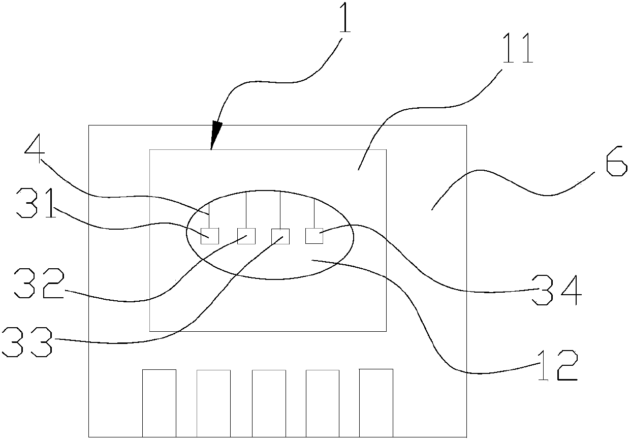
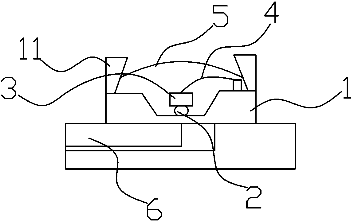
[0021] Such as Figure 1-2 As shown, the light source lighting module includes a wafer 3 , a bracket and a printed circuit board 6 . The support is a plastic support 1. In this embodiment, the material of the plastic bracket 1 is polycarbonate. In practical applications, acrylonitrile-butadiene-styrene copolymers can also be used. The plastic support 1 is a cube provided with an oval groove 12 . The oval groove 12 of the plastic support 1 is coated with silver glue 2, the wafer 3 is pasted on the silver glue 2, and the wafer 3 is fixed by baking. The silver glue 2 can not only fix the wafer 3 but also conduct electricity. In addition, the silver glue 2 can quickly dissipate the heat generated by the wafer 3 when it emits light. The wafer 3 includes a red light wafer 31 , a green light wafer 32 , a blue light wafer 33 , and an infrared light wafer 34 . The four wafers 3 are arranged in a line, and the arrangement in a line makes the reflected light of the red light wafer 3...


PUM


Abstract

The invention provides a light source light emitting module which comprises a wafer, a support and a printed circuit board, wherein the wafer is connected to the support, the wafer comprises a red light wafer, a green light wafer, a blue light wafer and an infrared light wafer, and the support is connected with the printed circuit board. Due to the fact that the infrared light wafer is additionally arranged based on the arrangement of the red light wafer, the green light wafer and the blue light wafer, the application range of the light source light emitting module is wider. The light source light emitting module can be used on scanning equipment made of materials sensitive to infrared light such as a currency detector.

Description

technical field [0001] The invention belongs to a light source module, and more specifically relates to a light source module including an infrared light source. Background technique [0002] There are only red light, green light and blue light in the light source lighting module of the prior art, and there is no infrared light, and the material of the light source light emitting module of the prior art is all metal materials, a light source needs to add a pin, and at the same time The entire width needs to be increased, and the cost is higher. Contents of the invention [0003] The invention provides a light source lighting module, which includes a wafer, a bracket and a printed circuit board. The wafer is connected to the bracket. Connected with the printed circuit board, the red light wafer, green light wafer, blue light wafer and infrared light wafer are located in a straight line. [0004] Its beneficial effects are: adding infrared light wafers on the basis of red ...

Claims


Application Information

Patent Timeline
IPC IPC(8): F21S2/00F21V19/00
Inventor 席文杰张景超谢炎忠廖国富
Owner 敦南科技(无锡)有限公司
Why Eureka
Try Eureka