Part mounting device and method

A technology for mounting devices and components, applied in the direction of electrical components, electrical components, etc., can solve problems such as increased vibration, difficulty in increasing the moving speed of the mounting head, and large-scale component mounting devices, achieving the effect of a high configuration structure

Inactive Publication Date: 2013-10-23
PANASONIC CORP
View PDF1 Cites 2 Cited by
  • Summary
  • Abstract
  • Description
  • Claims
  • Application Information

AI Technical Summary

Problems solved by technology

In addition, since the top frame is located at a position deviated from the base (base) of the component mounting device, the amount of vibration due to the exciting force tends to increase
Therefore, it is difficult to control the movement of the mounting head with high precision, and it is also difficult to increase the movin

Method used


Image

  • Part mounting device and method
  • Part mounting device and method
  • Part mounting device and method

Examples


Embodiment Construction

[0050] Hereinafter, embodiments according to the present invention will be described in detail with reference to the drawings. It should be noted that the present invention is not limited by this embodiment.

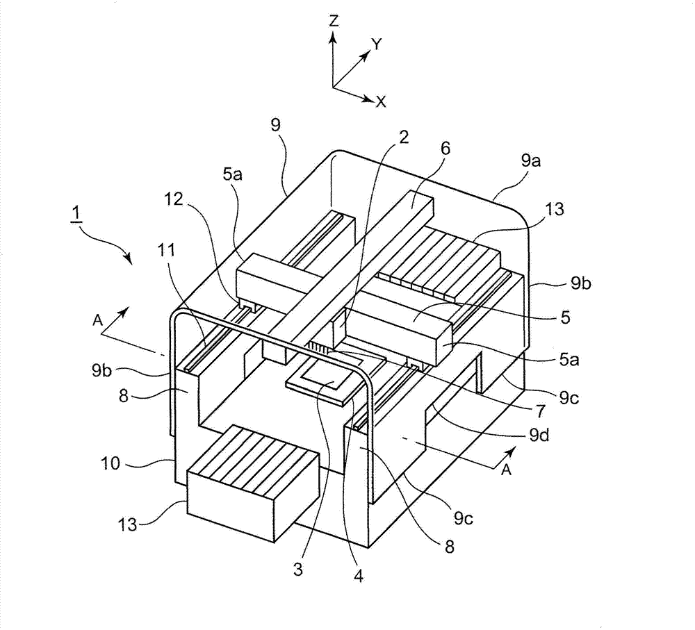
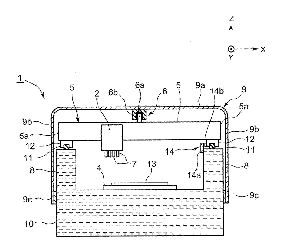
[0051] A perspective view of the appearance of the component mounting device 1 according to one embodiment of the present invention is shown in figure 1 . in addition, figure 1 The A-A line sectional view of the component mounting device 1 is shown in figure 2 . Below, refer to figure 1 and figure 2 , the configuration of the component mounting apparatus 1 according to this embodiment will be described. It should be noted that, in the following description, the X-axis direction and the Y-axis direction are directions along the surface of the substrate (horizontal direction) and are perpendicular to each other, and the Z-axis direction is a direction perpendicular to the X-axis direction and the Y-axis direction. The direction of intersection (vertical direction)...


PUM


Abstract

The invention provides a part mounting device and a method. The structure that is adopted is that two ends of an X-axis beam which supports a mounting head are supported through an X-axis beam supporting body arranged at a lower side of the X-axis beam, and driving force in an Y-axis direction is applied to a central upper part of the X-axis beam through a Y-axis driving part supported by a Y-axis driving part supporting body which is formed separately from the X-axis beam supporting body and arranged at an upper side of the X-axis beam. Thus, a transmission amount of exciting force towards the Y-axis driving part supporting body which is generated due to movement of the mounting head or the X-axis beam can be reduced, thereby improving control precision of movement of the mounting head.

Description

technical field [0001] The present invention relates to a component mounting device and method for mounting components on a substrate using a mounting head supported on an X-axis beam. Background technique [0002] Conventionally, devices of various configurations are known as such component mounting devices. For example, in the component mounting apparatus of patent document 1, the structure which supports the mounting head and the X-axis beam by the ceiling frame is employ|adopted. Specifically, the top frame supports the upper parts of both ends of the X-axis beam that supports the mounting head so that it can move along the X-axis direction via a linear motion guide mechanism extending along the Y-axis direction, so that it can move along the Y-axis direction. Axis direction movement. The top frame is provided with a Y-axis driving unit that moves the X-axis beam in the Y-axis direction. The X-axis beam is moved in the Y-axis direction by the Y-axis drive unit, and th...

Claims


Application Information

Patent Timeline
IPC IPC(8): H05K13/04
Inventor 城户一夫
Owner PANASONIC CORP
Why Eureka
Try Eureka