Laminated piezoelectric body
A piezoelectric body and piezoelectric element technology, applied in the direction of circuits, electrical components, piezoelectric/electrostrictive/magnetostrictive devices, etc., can solve the complicated grinding process, the decline in yield, and the difficulty in improving the piezoelectric element segment Productivity and other issues, to achieve the effect of ensuring productivity, improving reliability, and improving durability
- Summary
- Abstract
- Description
- Claims
- Application Information
AI Technical Summary
Problems solved by technology
Method used
Image
Examples
Deformed example 1
[0084] Such as Figure 8 As shown, in the piezoelectric element segment 60 of Modification 1, the lower contact portion 28A of the piezoelectric ceramic 13 of the first embodiment is replaced with the lower contact portion 61 , and the other structures are the same as those of the piezoelectric element segment 12A of the first embodiment.
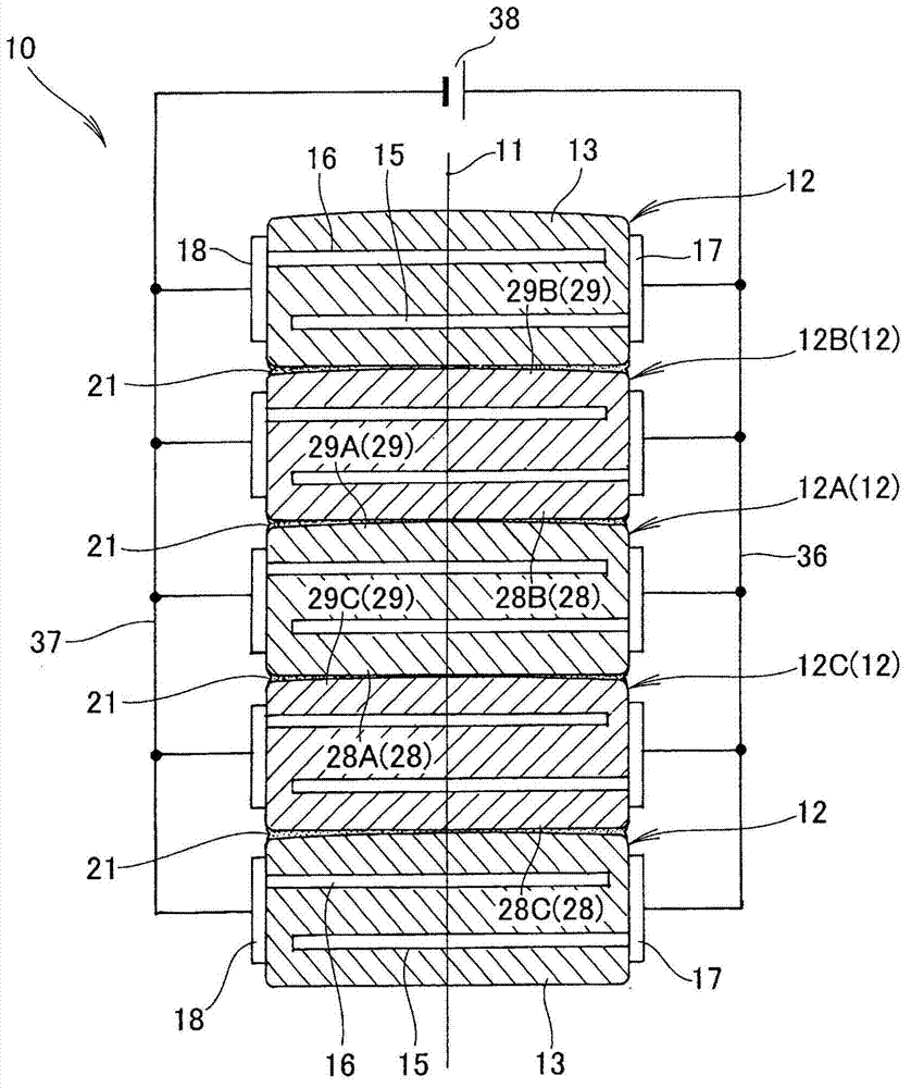
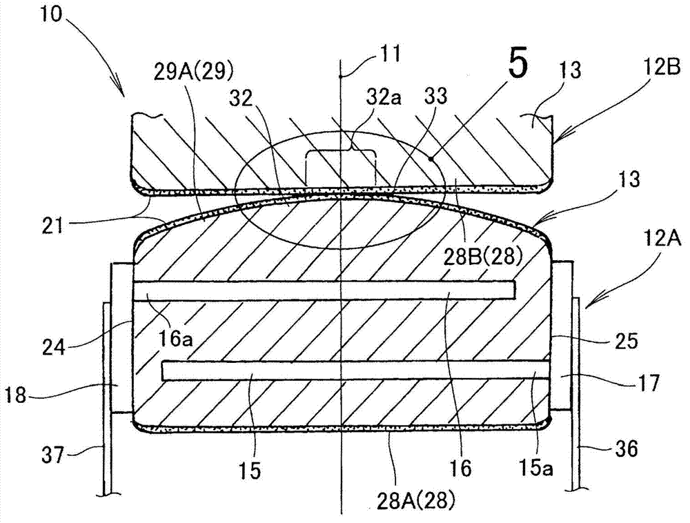
[0085] The lower contact portion 61 is formed in a curved shape so as to protrude downward, and has a central convex portion 62 at the center. The central convex portion 62 is vertically symmetrical to the central convex portion 32 of the first embodiment. By providing the central convex portion 62 at the center of the lower contact portion 61, the central convex portion 62 can be directed toward the upper contact portion 29C of the piezoelectric element segment 12C ( figure 1 ) of the central protrusion.
[0086] The central convex portion 62 is a portion of the lower contact portion 61 formed in a curved shape so as to protrude downward...
Deformed example 2)
[0088] Such as Figure 9 As shown, in the piezoelectric element segment 70 of Modification 2, the upper contact portion 29A of the piezoelectric ceramic 13 of the first embodiment is replaced with the upper contact portion 71 , and the other structures are the same as those of the piezoelectric element segment 12A of the first embodiment.
[0089] The upper contact portion 71 is formed in a substantially trapezoidal shape so as to protrude upward and has a central convex portion 72 at the center. The central convex portion 72 has: a left cone surface (cone surface) 73 formed as an ascending slope from the left end portion 71 a of the upper contact portion 71 toward the axis 11; The right end portion 71 b is formed as an ascending slope toward the axis 11 ; and a horizontal flat surface 75 is formed between the upper end portion of the left tapered surface 73 and the upper end portion of the right tapered surface 74 .
[0090] This central convex portion 72 has: a left interse...
Deformed example 3)
[0098] Such as Figure 12 As shown, the piezoelectric element segment 80 of Modification 3 is the lower contact portion 78 of the piezoelectric element segment 70 of Modification 2 ( Figure 9 ) is replaced by the lower contact portion 81 , and the other structures are the same as those of the piezoelectric element segment 70 of Modification 2. The lower contact portion 78 of the piezoelectric element segment 70 is a portion formed flat like the lower contact portion 28A of the first embodiment.
[0099] The lower contact portion 81 of the piezoelectric element segment 80 is formed in a substantially trapezoidal shape so as to protrude downward and has a central convex portion 82 in the center. The central convex portion 82 is vertically symmetrical to the central convex portion 72 of Modification 2. As shown in FIG. By providing the central convex portion 82 at the center of the lower contact portion 81, the central convex portion 82 can be directed toward the upper contact...
PUM
 Abstract
Description
Claims
Application Information
 - R&D
- Intellectual Property
- Life Sciences
- Materials
- Tech Scout
- Unparalleled Data Quality
- Higher Quality Content
- 60% Fewer Hallucinations
Browse by: Latest US Patents, China's latest patents, Technical Efficacy Thesaurus, Application Domain, Technology Topic, Popular Technical Reports.
© 2025 PatSnap. All rights reserved.Legal|Privacy policy|Modern Slavery Act Transparency Statement|Sitemap|About US| Contact US: help@patsnap.com


