
Camera lens shadow correction coefficient determination method and device, and camera lens shadow correction method and device

A lens shading and correction coefficient technology, applied in the field of image processing, can solve the problem of unsatisfactory lens shading correction effect, etc., and achieve the effect of good correction effect, simple implementation method, and small implementation area.

Active Publication Date: 2013-10-30
BYD SEMICON CO LTD
View PDF9 Cites 24 Cited by
  • Summary
  • Abstract
  • Description
  • Claims
  • Application Information

AI Technical Summary

Problems solved by technology

[0004] The purpose of the present invention is to at least solve the technical problem of unsatisfactory lens shading correction effect existing in the prior art, and provide a lens shading correction coefficient determination method, lens shading correction method and device with better correction effect

Method used


Image

  • Camera lens shadow correction coefficient determination method and device, and camera lens shadow correction method and device
  • Camera lens shadow correction coefficient determination method and device, and camera lens shadow correction method and device
  • Camera lens shadow correction coefficient determination method and device, and camera lens shadow correction method and device

Examples


Embodiment 1

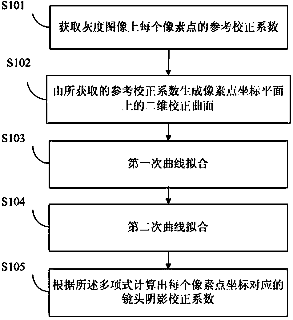
[0033] Such as figure 1 As shown, the lens shading correction coefficient determination method provided by Embodiment 1 of the present invention includes the following steps:

[0034] S101: Obtain a reference correction coefficient for each pixel on the grayscale image.

[0035] In the specific implementation, after taking a grayscale image with uniform brightness distribution with the lens, the real pixel value of each pixel point of the captured image is obtained, the brightest point in the grayscale image is selected as the standard value, and the difference between the standard value and the photographed value is calculated. The ratio of the real pixel values ​​of each pixel of the image to obtain the reference correction coefficient of each pixel. The grayscale image refers to an image in which each pixel has only one sampled color. In this embodiment, it is assumed that the size of the lens is 1200 rows*1600 columns, and a grayscale image with a size of 1200*1600 is ca...

Embodiment 2

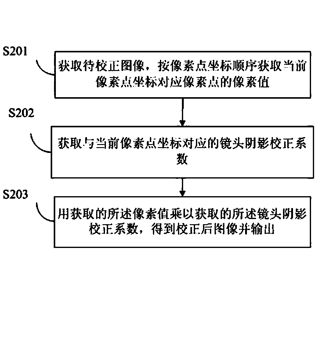
[0068] Such as figure 2 As shown, the flow of the lens shading correction method provided by Embodiment 2 of the present invention includes the following steps:

[0069] S201: Acquire the image to be corrected, and acquire the pixel values ​​of the pixels corresponding to the current pixel coordinates in order of pixel coordinates.

[0070] S202: Obtain a lens shading correction coefficient corresponding to the current pixel coordinates.

[0071] Wherein, the determination method of the lens shading correction coefficient is:

[0072] Obtain the reference correction coefficient of each pixel on the grayscale image; in specific implementation, after taking a grayscale image with uniform brightness distribution with the lens, the real pixel value of each pixel of the captured image is obtained, and the grayscale image is selected The brightest point is the standard value, and the ratio of the standard value to the real pixel value of each pixel in the captured image is calcul...

Embodiment 3

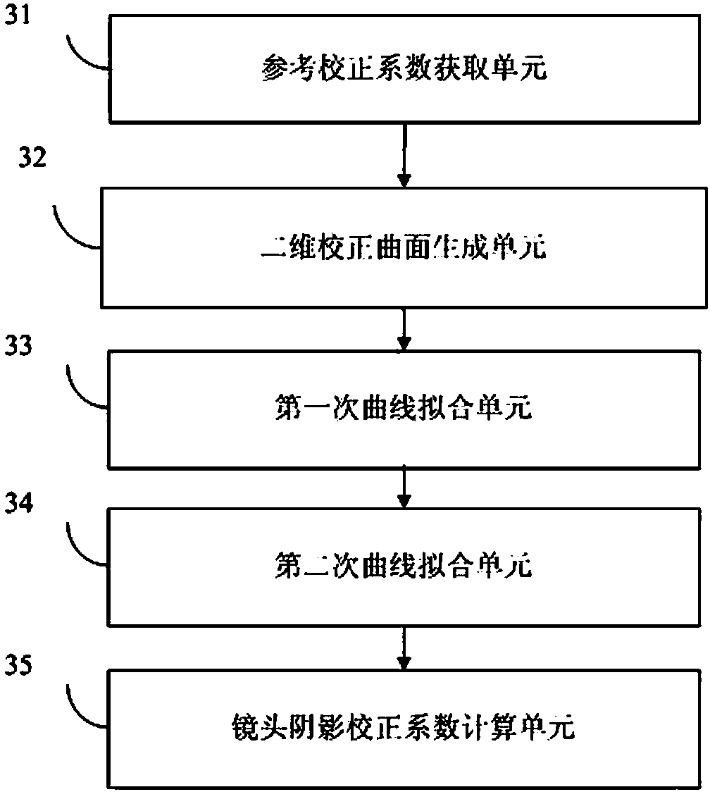
[0089] Such as image 3 As shown, it is a lens shading factor determination device provided by Embodiment 3 of the present invention, which includes

[0090] A reference correction coefficient acquisition unit 31, configured to acquire a reference correction coefficient for each pixel on the grayscale image;

[0091] The two-dimensional correction curved surface generation unit 32 is configured to generate a two-dimensional correction curved surface on the pixel point coordinate plane from the acquired reference correction coefficients. In a specific implementation, a two-dimensional correction surface on the pixel coordinate plane is generated according to the abscissa, ordinate and reference correction coefficient of each pixel;

[0092] The first curve fitting unit 33 is configured to perform unary high-power polynomial fitting on each row on the two-dimensional calibration surface. In a specific implementation, a unary high-power polynomial with the ordinate of the pixel...


PUM


Abstract

The invention discloses a camera lens shadow correction coefficient determination method and device, and a camera lens shadow correction method and device. The camera lens shadow correction coefficient determination method includes the steps of obtaining the reference correction coefficient of each pixel on a gray level image, generating a two-dimension correction curved surface, conducting primary curve fitting, conducting secondary curve fitting, and calculating the camera lens shadow correction coefficient corresponding to each pixel coordinate. The invention further discloses the camera lens shadow correction coefficient determination device. The camera lens shadow correction method includes the steps of obtaining an image to be corrected, obtaining a camera lens shadow correction coefficient, and obtaining the corrected image by the way that a pixel value is multiplied by the camera lens shadow correction coefficient. The invention further discloses the camera lens shadow correction device. The camera lens shadow correction coefficient determination method and device, and the camera lens shadow correction method and device are suitable for conducting camera lens shadow correction on images shot by various camera lenses, the correction effect is good, the implementation method is simple, and hardware implementation area is small.

Description

technical field [0001] The invention relates to the field of image processing, in particular to a method for determining lens shading correction coefficients, a lens shading correction method and a device. Background technique [0002] As we all know, when microlenses are used for imaging, the brightness of the light collected by the pixels on the image sensor is related to the angle of the incident light. The parts near the center of the lens will be brighter, while the parts near the edge will be darker. This will make the light signal collected by the pixels on the edge weak. In order to correct this phenomenon, a method is needed to deal with it. Lens Shading Correction (Lens Shading Correction) is to use a certain algorithm to convert Correction and removal of shadows caused by optical reasons. [0003] The principle of lens shading correction is to find out the correction coefficient of each pixel of the lens, and then calculate the actual value based on the current s...

Claims


Application Information

Patent Timeline
Patent Type & Authority Applications(China)
IPC IPC(8): G06T7/00H04N9/04
Inventor 王毫杰申冬彭茂胡文阁
Owner BYD SEMICON CO LTD
Learn More