
Circuit board and method of manufacturing circuit board

A technology of circuit substrate and manufacturing method, which is applied in the directions of printed circuit manufacturing, multilayer circuit manufacturing, printed circuit dielectric, etc., can solve problems such as inability to ensure the insulation of metal shells, achieve the effect of improving insulation and realizing structure

Inactive Publication Date: 2013-10-30
KOITO MFG CO LTD
View PDF7 Cites 1 Cited by
  • Summary
  • Abstract
  • Description
  • Claims
  • Application Information

AI Technical Summary

Problems solved by technology

[0012] If the recess h or the hole i is formed on the insulating layer g, good insulation against the metal case cannot be ensured in a state of being bonded to the metal case.

Method used


Image

  • Circuit board and method of manufacturing circuit board
  • Circuit board and method of manufacturing circuit board
  • Circuit board and method of manufacturing circuit board

Examples


Embodiment Construction

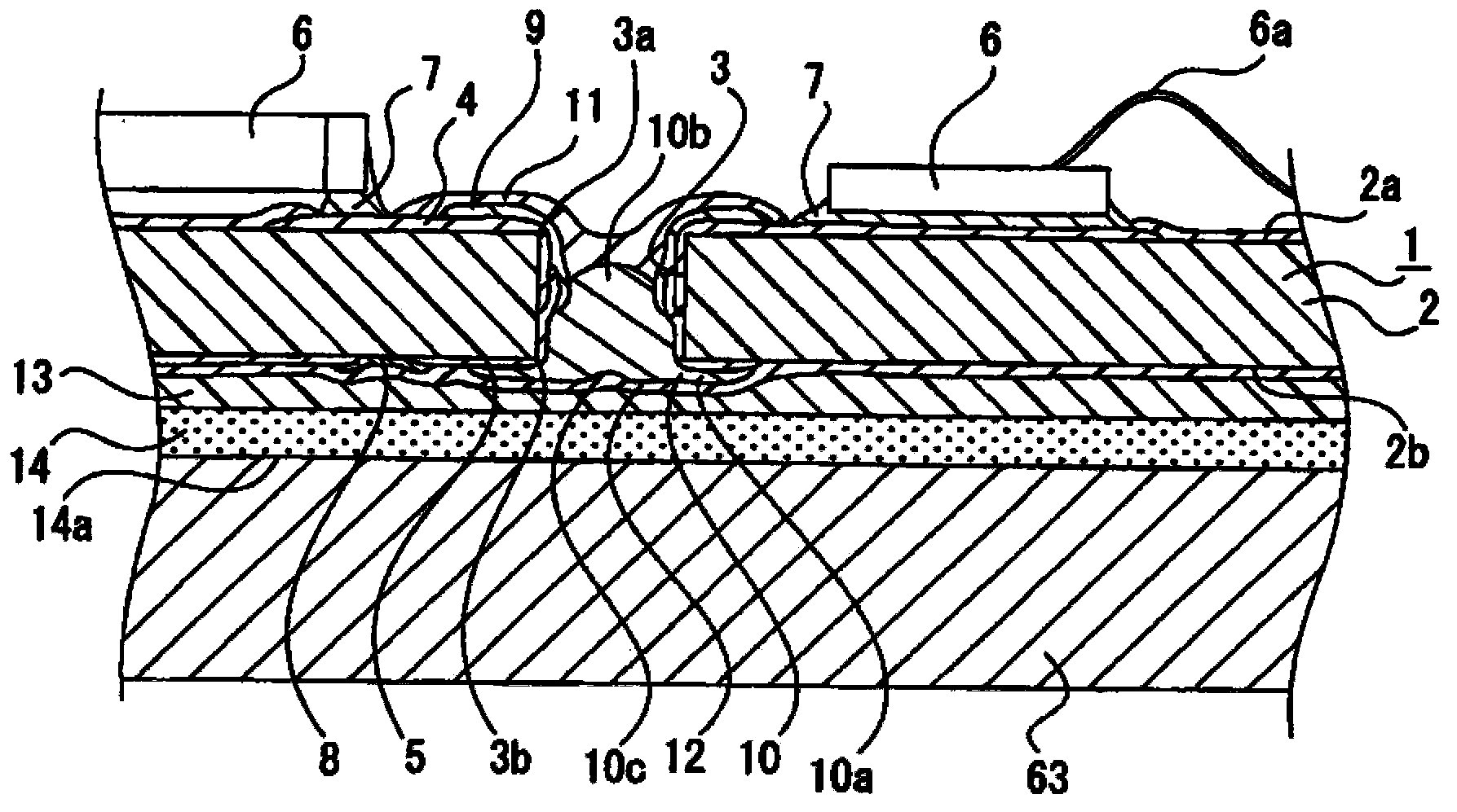
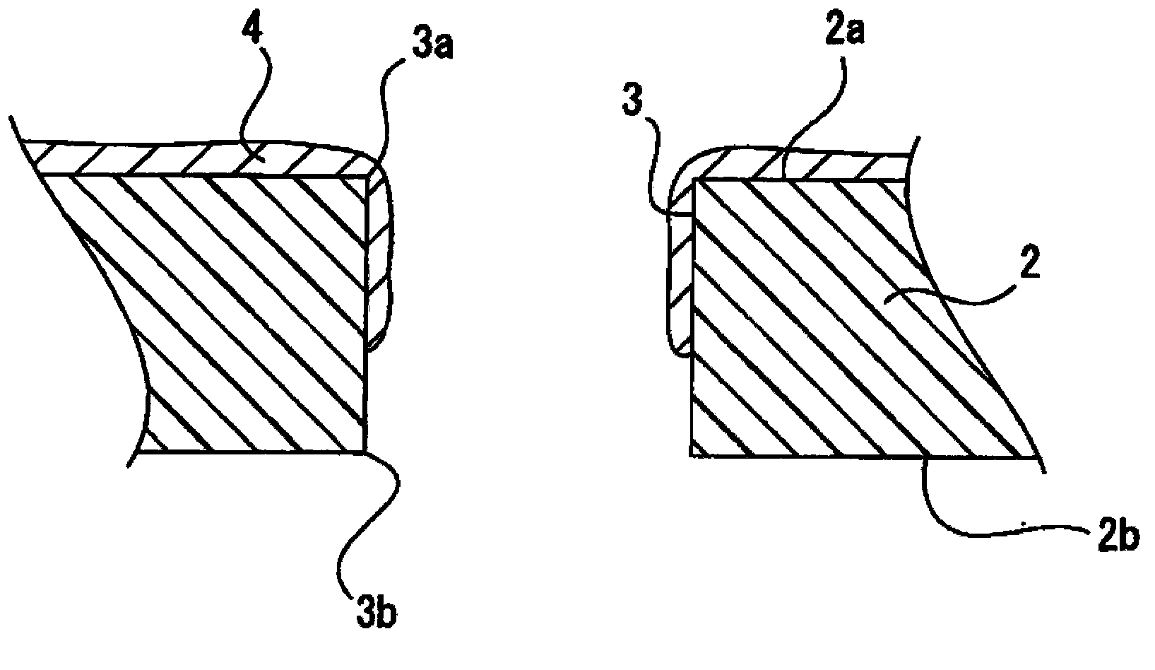
[0043] Hereinafter, preferred embodiments for carrying out the present invention will be described with reference to the drawings.

[0044] In the following description, the direction in which the light source of the vehicle lamp provided with the circuit board faces, that is, the direction in which light is emitted from the light source, is referred to as the front, and the front, rear, up, down, left, and right directions are indicated.

[0045] In addition, the directions of front, back, up, down, left, and right shown below are assumed for convenience of description, and implementation of the present invention is not limited to the above directions.

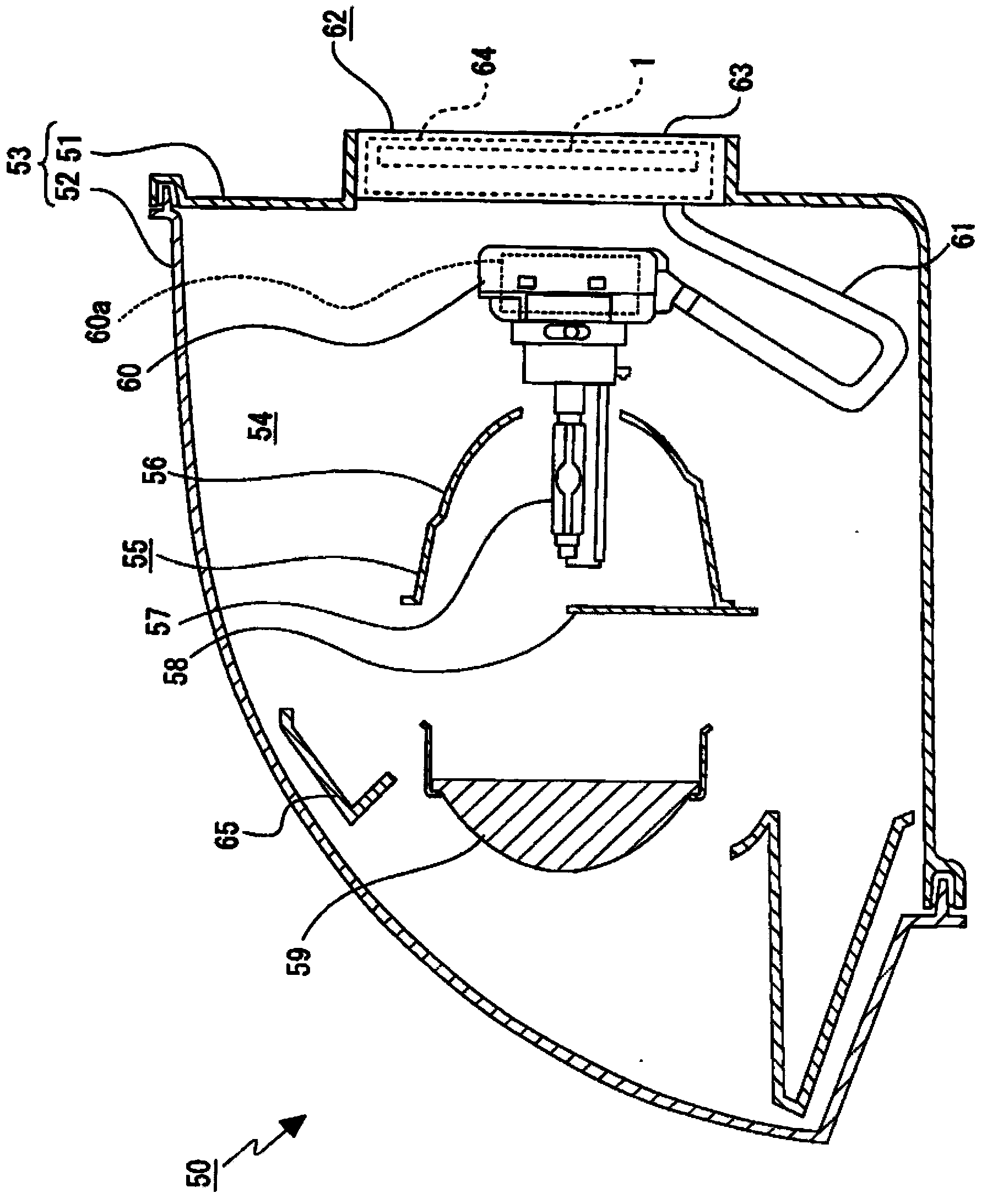
[0046] The circuit board 1 is provided, for example, as a part of electrical components arranged in a vehicle lamp 50 such as a vehicle headlamp.

[0047] The vehicle lamps 50 are mounted on both left and right ends of the front end of the vehicle body.

[0048] Vehicle lamps 50 such as figure 1 The shown lamp body 51 has ...


PUM


Abstract

The invention provides a circuit board and a method for manufacturing the circuit board, in which good electrical continuity can be secured between the conductive layers and high insulation of the circuit board from a metal case can be attained. The circuit board includes an insulative substrate configured with a through-hole which communicates a first surface on which an electronic component is mounted with a second surface opposite to the first surface; a first conductive layer which extends from the first surface to the through-hole to electrically connect the electric component; a second conductive layer which extends from the second surface to the through-hole in which the second conductive layer is electrically connected with the first conductive layer; a a resistance layer which is formed on the second surface and electrically connected to the second conductive layer; a second surface stacking conductive layer which extends form the second surface to the through-hole, covers the the second conductive layer, and fills at least part of the through-hole; a second face protective glass layer covering the second conductive layer, the second surface stacking conductive layer and the resistance layer; and an adhesive layer formed between the second face protective glass layer and the internal surface of the metal case.

Description

technical field [0001] The invention relates to a circuit substrate and a method for manufacturing the circuit substrate. Specifically, it relates to the technical field of using a second-side laminated conductive layer covering a second-side conductive layer to block at least a part of a via hole to ensure electrical conduction between the first-side conductive layer and the second-side conductive layer. Good conductivity between layers, and improved insulation relative to metal shells. Background technique [0002] There is a technique in which an electric component covered with a metal case is provided in a vehicle lamp such as a vehicle headlamp. As an electrical component, for example, there is a lighting device for a discharge lamp when the discharge lamp is used as a light source of a vehicle lamp. [0003] In such an electrical component, a circuit board functioning as a lighting circuit is provided, and the circuit board is fixed to the inner surface of the metal ...

Claims


Application Information

Patent Timeline
Patent Type & Authority Applications(China)
IPC IPC(8): H05K1/02H05K1/11H05K3/42
CPCH05K2203/1572H05K2203/159H05K3/4061H05K2201/10113H05K2203/1563H05K1/0298H05K1/167H05K2201/0175H05K3/0061H05K2201/09563H05K1/0209H05K1/16H05K3/46F21S48/1186H05K2201/017H05K3/28H05K1/0265H01L2224/48091H01L2224/73265F21S41/17Y10T29/49165H01L2924/00014
Inventor 寺冈慎次土屋俊幸清水伸幸
Owner KOITO MFG CO LTD
Learn More