Optical fiber

A technology of optical fiber core and core wire, applied in the direction of glass optical fiber, cladding optical fiber, light guide, etc., can solve the problem of increased transmission loss of optical fiber, and achieve the effect that the transmission loss is not easy to increase

Active Publication Date: 2013-10-30
FURUKAWA ELECTRIC CO LTD
View PDF8 Cites 1 Cited by
  • Summary
  • Abstract
  • Description
  • Claims
  • Application Information

AI Technical Summary

Problems solved by technology

[0003] The optical fiber will increase the transmission loss due to various external stresses and the resulting microbends

Method used


Image

  • Optical fiber
  • Optical fiber
  • Optical fiber

Examples


Embodiment )

[0047] Hereinafter, examples of the optical fiber core wires described in the above embodiments will be described.

[0048] In the above-mentioned configuration of the optical fiber core wire 1, an optical fiber core wire 1 with different Young's modulus of the first coating layer 31 and the dissolution rate of the coating resin 3 was produced, and the presence of voids, solvent resistance, and microbending resistance were investigated. characteristic.

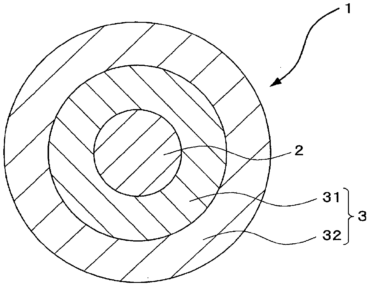
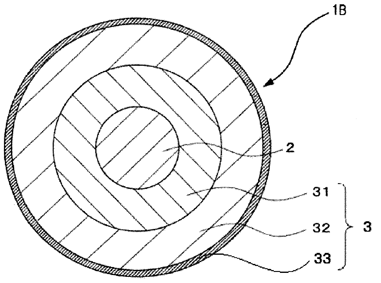
[0049] In the manufacture of the sample fiber core wire, as the glass optical fiber 2, the outer diameter (diameter) of about For a 125 μm glass optical fiber, a first coating layer 31 is formed on the outer circumference, and a second coating layer 32 is further formed on the outer circumference, to produce an optical fiber core wire 1. The outer diameter of the first coating layer 31 is 195 μm, and the outer diameter of the second coating layer 32 is 245 μm. These values ​​are examples and can be changed as appropriate.

[0050]...

Embodiment 1

[0070] In Example 1 (Sample No. 2), the first coating layer 31 and the second coating layer 32 use a urethane acrylate ultraviolet curable resin, and each of the first coating layer 31 and the second coating layer 32 The Young's modulus, the dissolution rate of the coating resin 3, the molecular weight of the oligomer, the type of diluting monomer, the ratio of the chain transfer agent, etc., were adjusted to adjust the Young's modulus PY of the first coating layer 31 to 0.14 MPa , The elution rate E when the coating resin 3 is immersed in 60°C warm water for 168 hours is adjusted to 2.4% by mass. In addition, 168 hours are used because the elution from the coating resin is substantially saturated by 168 hours.

Embodiment 2

[0071] In Example 2 (Sample No. 3), the Young’s modulus PY of the first coating layer 31 was adjusted to 0.20 MPa in addition to adjusting the molecular weight of the oligomer, the type of diluting monomer, the ratio of the chain transfer agent, etc., and the coating The resin 3 was the same as in Example 1 above except that the elution rate E when immersed in 60°C warm water for 168 hours was adjusted to 1.8% by mass.


PUM


Abstract

The present invention provides an optical fiber in which transmission loss is not easily increased when the optical fiber is dipped in water and then dried and also which has a solvent resistant property and a micro-bend resistant property. An optical fiber according to one embodiment of the present invention is an optical fiber in which at least two layers of coating resin coat the circumference of a glass optical fiber. When a Yang's modulus of the first coating layer of the coating resin is defined by PY (MPa) and an elution rate of the coating resin after dipping in 60° C. hot water for 168 hours is defined by E (mass·%), a formula of 1.8@E@8.61×PY+1.40 is satisfied.

Description

Technical field [0001] The invention relates to an optical fiber core wire, in particular to an optical fiber core wire accommodated in an optical fiber cable. Background technique [0002] In recent years, with the progress of FTTH (Fiber To The Home), in order to reduce the transmission loss of the optical fiber, it is required to improve the microbending resistance of the optical fiber. [0003] The optical fiber will increase the transmission loss due to various external stresses and microbending caused by it. In order to protect the optical fiber from this external stress, the glass optical fiber is generally coated with a resin coating composed of a two-layer structure. In addition, an optical fiber coated with a glass optical fiber is called an optical fiber core wire. [0004] As an optical fiber core wire with a coating layer having a two-layer structure, the following optical fiber core wire is disclosed: When the optical fiber core wire is immersed in warm water at 60°C ...

Claims


Application Information

Patent Timeline
Patent Type & Authority Applications(China)
IPC IPC(8): C03C25/24G02B6/44
CPCC03C25/50G02B6/02395G02B6/4403
Inventor 斋藤稔笠原稔望月浩二田中广树中岛康雄
Owner FURUKAWA ELECTRIC CO LTD
Why Eureka
Try Eureka