Fiber optic core wire
An optical fiber core, glass optical fiber technology, applied in glass optical fibers, cladding optical fibers, light guides, etc., can solve the problem of increasing the transmission loss of optical fibers, and achieve the effect that the transmission loss is not easy to increase
- Summary
- Abstract
- Description
- Claims
- Application Information
AI Technical Summary
Problems solved by technology
Method used
Image
Examples
Embodiment )
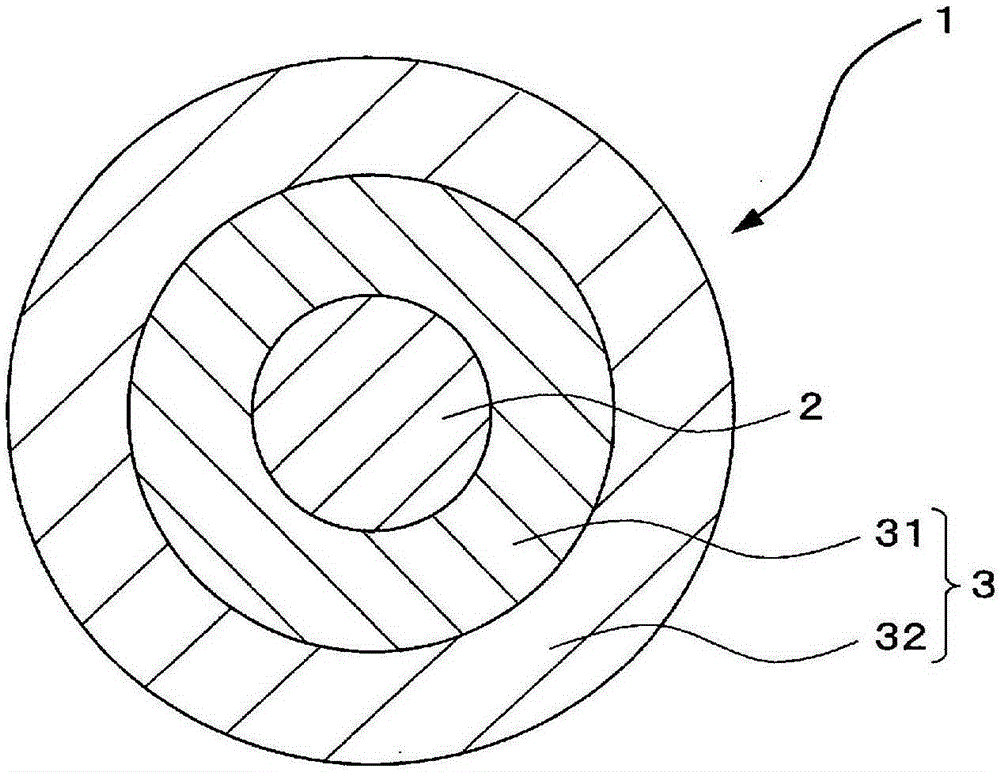
[0047] Examples of the optical fiber core wires described in the above embodiments will be described below.
[0048] In the configuration of the optical fiber 1 described above, an optical fiber 1 having a difference in the Young's modulus of the first coating layer 31 and the elution rate of the coating resin 3 was produced, and the occurrence of voids, solvent resistance, and microbending resistance were investigated. characteristic.
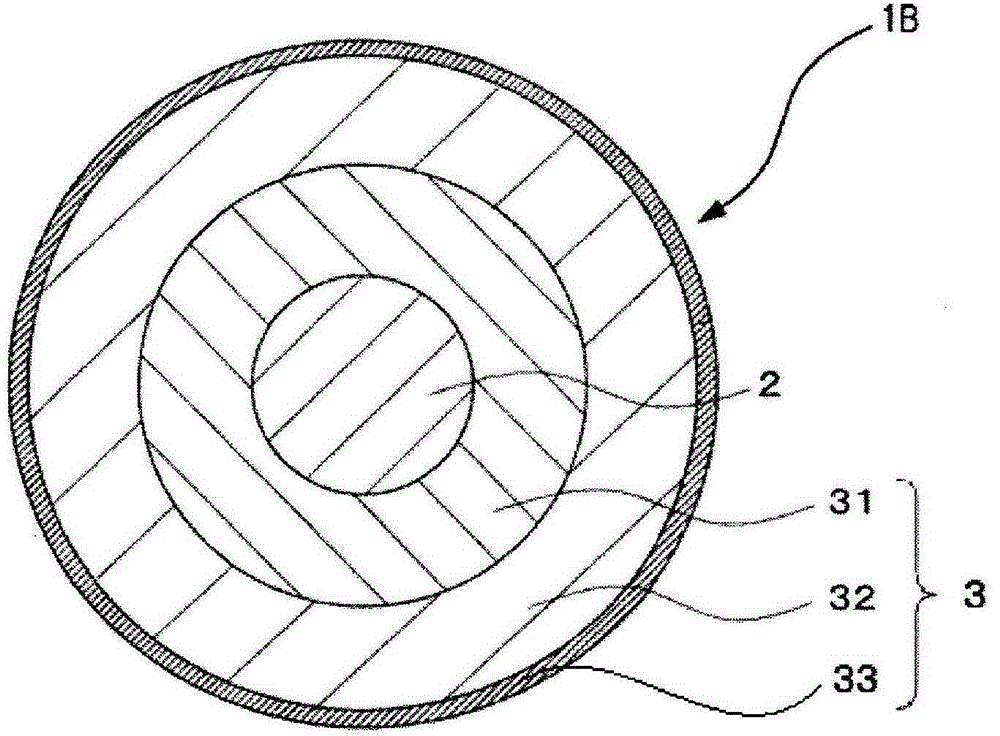
[0049] In the production of the optical fiber core wire of the sample, as the glass optical fiber 2, an outer diameter (diameter) of approximately A 125 μm glass optical fiber was formed with a first coating layer 31 on its outer periphery, and a second coating layer 32 was further formed on its outer periphery to manufacture an optical fiber core wire 1 . The outer diameter of the first coating layer 31 is 195 μm, and the outer diameter of the second coating layer 32 is 245 μm. These values are examples and may be changed appropriately. ...
Embodiment 1
[0070] In Example 1 (sample No. 2), the first coating layer 31 and the second coating layer 32 use urethane acrylate ultraviolet curable resin, and each of the first coating layer 31 and the second coating layer 32 Young's modulus, the dissolution rate of the coating resin 3, adjust the molecular weight of the oligomer, the type of diluent monomer, the proportion of the chain transfer agent, etc., so as to adjust the Young's modulus PY of the first coating layer 31 to 0.14MPa , the elution rate E when the coating resin 3 was soaked in 60° C. warm water for 168 hours was adjusted to 2.4% by mass. In addition, 168 hours was used because the elution from the coating resin was substantially saturated by the elapse of 168 hours.
Embodiment 2
[0071] Example 2 (Sample No. 3) In addition to adjusting the molecular weight of the oligomer, the type of diluent monomer, the proportion of the chain transfer agent, etc., the Young’s modulus PY of the first coating layer 31 was adjusted to 0.20 MPa, and the coating The elution rate E of the resin 3 when immersed in warm water at 60° C. for 168 hours was the same as in the above-mentioned Example 1, except that it was adjusted to 1.8% by mass.
PUM
 Abstract
Description
Claims
Application Information
 - R&D
- Intellectual Property
- Life Sciences
- Materials
- Tech Scout
- Unparalleled Data Quality
- Higher Quality Content
- 60% Fewer Hallucinations
Browse by: Latest US Patents, China's latest patents, Technical Efficacy Thesaurus, Application Domain, Technology Topic, Popular Technical Reports.
© 2025 PatSnap. All rights reserved.Legal|Privacy policy|Modern Slavery Act Transparency Statement|Sitemap|About US| Contact US: help@patsnap.com


