Supercharge Your Innovation With Domain-Expert AI Agents!

Lock modules for motor vehicles

A lock module and lock part technology, applied in the field of lock modules, can solve the problems of increasing space problems, increasing the number, increasing and the like

Active Publication Date: 2016-04-06
KIEKERT AG
View PDF2 Cites 0 Cited by
  • Summary
  • Abstract
  • Description
  • Claims
  • Application Information

AI Technical Summary

Problems solved by technology

In addition, the increased installation costs are due to the increased number of modules and other components such as side impact protection, which increases the space problem
In addition, the diversity of vehicle door types has also increased, which also leads to increased requirements for installation

Method used


Image

  • Lock modules for motor vehicles

Examples


Embodiment Construction

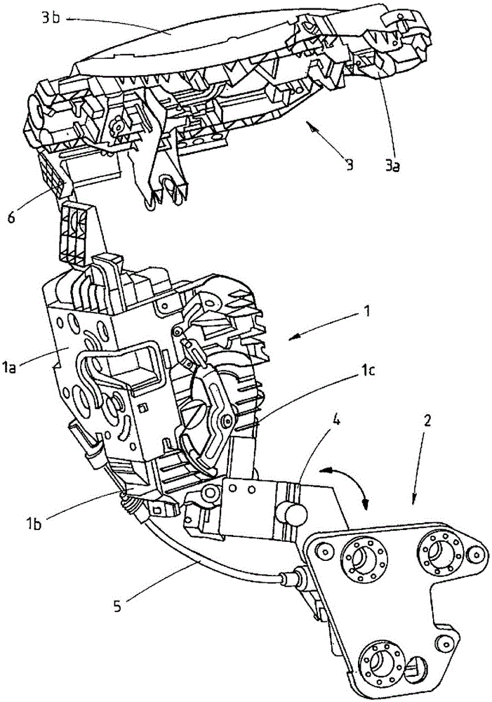
[0031] figure 1 A lock module is shown, comprising: a servo lock device 1 , an electric drive 2 for the lock device 1 , and a handle module 3 with a handle plate 3 a and a handle 3 b. The driving device 2 is rotatably mounted on the servo lock device 1 by means of a connecting plate 4 . The servo lock device includes a lock plate la, a lock housing lb and a lock cover lc. A locking unit is provided in the rotationally movable connection between the servo locking device 1 and the electric drive 2 , which locking unit enables locking in at least two different positions. In general, two different locking positions are sufficient to considerably simplify the installation. It may therefore even be preferable to lock or lock into only two different positions, so that only two different locking and / or locking arrangements of the drive device 2 relative to the actuating lock device 1 are possible. Operating errors are generally reduced in this way. Due to the limited number of loc...


PUM


Abstract

The present invention relates to a lock module. Object of the present invention is to provide a lock module, which can help reduce the cost of installation. To achieve the purpose, the lock module comprises a plurality of components, i.e., at least two components, the member is selected from: a locking device, in particular a servo lock device, which has a locking mechanism consisting of a locking claw and a rotating concave locking part; The lock module comprises at least one drive device, the drive device is dynamically installed inside the lock module. Thus, the drive may move relative to one or more of the remaining members of the lock module.

Description

technical field [0001] The invention relates to a lock module and a mounting method known, for example, from document DE 195 24 568 A1. The lock module is usually installed in a motor vehicle door, in particular a motor vehicle side door. Background technique [0002] A motor vehicle door lock with such a lock module is known from DE 19524568 A1, which comprises a locking element, a locking lever system, a lever system acting on the locking element and an outer handle. The locking element comprises a locking mechanism consisting of a rotary latch and a pawl. The locking mechanism is part of the motor vehicle lock. [0003] The rotary latch of the motor vehicle lock comprises a fork-shaped entry slot into which the locking pin of the door or the lid enters when the door or the lid is closed. The locking pin then turns the rotary latch from the open position into the closed position. If the rotary latch has reached the closed position, the locking pin can no longer leave t...

Claims


Application Information

Patent Timeline
Patent Type & Authority Patents(China)
IPC IPC(8): E05B79/04E05B79/06
CPCE05B79/04E05B79/06Y10T29/49002Y10T292/1082E05B17/0004E05B81/06
Inventor T·贝代尔B·德罗斯特H·戴施尔M·林德梅尔
Owner KIEKERT AG
Features
  • R&D
  • Intellectual Property
  • Life Sciences
  • Materials
  • Tech Scout
  • Unparalleled Data Quality
  • Higher Quality Content
  • 60% Fewer Hallucinations
Learn More