
Head-mounted display and misalignment correction method thereof

A display and head-mounted technology, applied in the field of head-mounted displays, can solve problems such as abnormal stereo vision, image dizziness, and audio-visual fatigue, and achieve the effect of suppressing abnormal stereo vision and high practical value

Inactive Publication Date: 2013-10-30
PANASONIC CORP
View PDF3 Cites 63 Cited by
  • Summary
  • Abstract
  • Description
  • Claims
  • Application Information

AI Technical Summary

Problems solved by technology

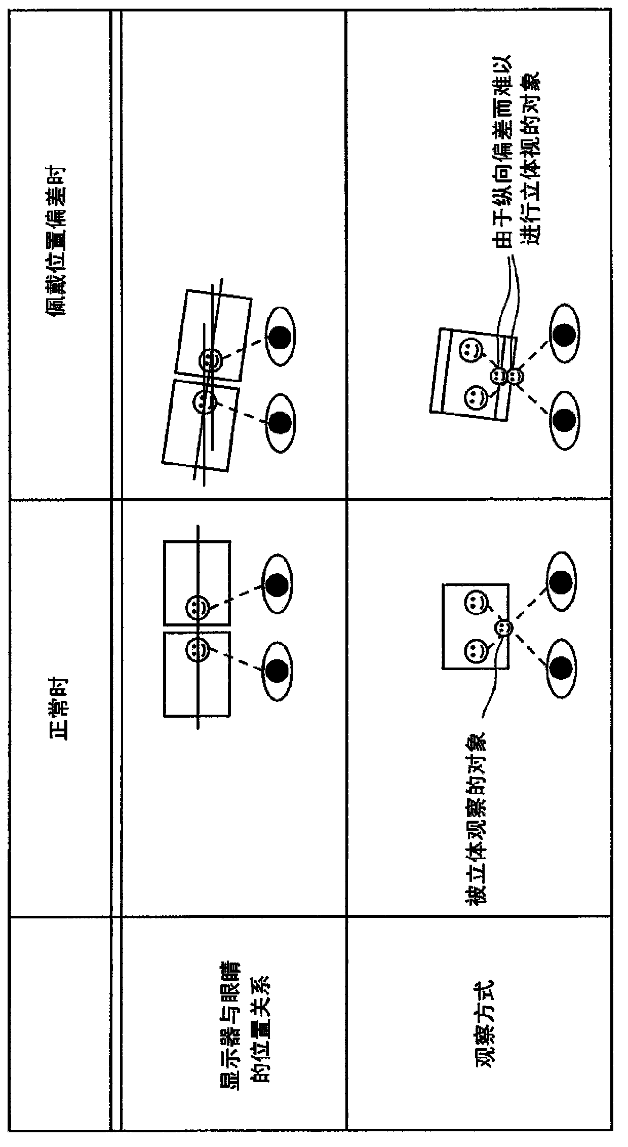
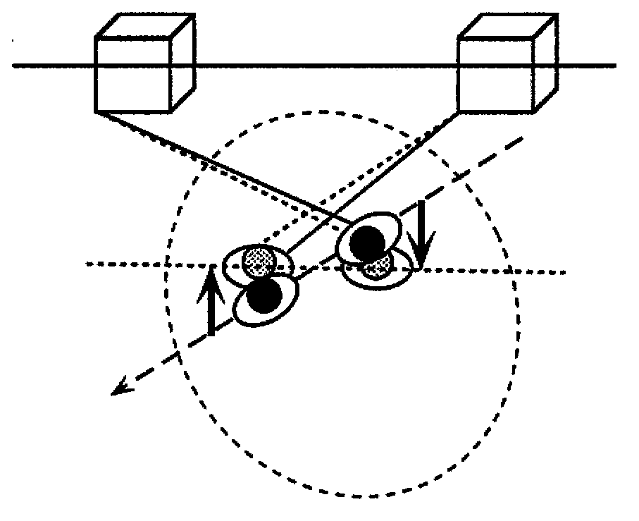
[0014] However, in the techniques of Patent Document 2 and Patent Document 3, when the HMD is mounted in a state deviated from the head, there is a problem of abnormality in stereoscopic viewing, fatigue during viewing, or video dizziness.

Method used


Image

  • Head-mounted display and misalignment correction method thereof
  • Head-mounted display and misalignment correction method thereof
  • Head-mounted display and misalignment correction method thereof

Examples


Embodiment approach 1

[0072] First, the head-mounted display according to Embodiment 1 of the present invention and its positional deviation adjustment method will be described.

[0073] Figure 5 It is a block diagram of the head-mounted display 1 of this embodiment.

[0074] The head-mounted display 1 is an HMD capable of suppressing stereoscopic abnormalities, fatigue during viewing, or video dizziness of the viewer even when it is mounted away from the head. The head-mounted display 1 includes an input unit 110 , to accept an operation instruction from the viewer; the position obtaining unit 100 obtains the position of the inner corner of the eye and the pupil of the viewer; the eyeball position calibration unit 40 obtains the position of the inner corner of the eye and the pupil detected by the position obtaining unit 100, and obtains The standard position of the inner corner of the eye; the standard position storage unit 50 stores the pupil calculated by the eyeball position calibration unit...

Embodiment approach 2

[0172] Next, a head-mounted display according to Embodiment 2 of the present invention and a positional deviation adjustment method thereof will be described.

[0173] In Embodiment 1, the method of calculating the vector of the deviation when the HMD 1 deviates from the front of the eyeball regardless of the shape of the HMD 1 was described. However, HMD1 is usually supported by the convex part of the nose of the viewer. Figure 22 It is a figure which shows an example of the hardware structure of HMD1 of this embodiment. The left-eye display 80L is provided in front of the viewer's left eye, and the right-eye display 80R is provided in front of the viewer's right eye. A camera 10 for photographing the viewer's eyes is installed between the two displays. For an infrared camera, an infrared light emitting unit is provided adjacent to the camera 10 . Set the temples and nose pads for wearing and fixing the HMD1. The fulcrums of the HMD1 are the ears and the nose, and the ce...


PUM


Abstract

An HMD includes: a display which displays a three-dimensional video image; a position obtaining unit which measures a position of an inner corner or tail of an eye of a viewer with respect to the display; a standard position storage unit which obtains and stores, as a standard position relating to the position, the measured position of the inner corner or outer corner of the eye, in calibration for determining the standard position; a position gap detecting unit which detects, as a position gap, a difference between the standard position and a newly measured position of the inner corner or outer corner of the eye of the viewer viewing content with respect to the display; and an image processing unit which performs image processing on the 3D video image to be displayed on the display, to rotated or parallely move the 3D video image according to the detected position gap.

Description

technical field [0001] The present invention relates to a head-mounted display, in particular to a technology for displaying a three-dimensional image in the head-mounted display and a technology for adjusting its position deviation. Background technique [0002] A head-mounted image display device, namely a head-mounted display (Head Mounted Display: hereinafter also described as "HMD"), is used as a remote operating system display for operations in dangerous areas where humans cannot directly operate or operations in remote areas. , In addition, it is also used as a display for embedded game consoles, etc. Regarding embedded displays, goggle-type displays covering the eyes and fixed to the head have been proposed. In addition, as devices become smaller and lighter, more lightweight glasses-type displays have been proposed for portable video content viewing. . [0003] On the other hand, 3D video is widely used not only in movies, but also as video of TV content and game ...

Claims


Application Information

Patent Timeline
IPC IPC(8): H04N13/04G09G3/20G09G5/00G09G5/36G09G5/38H04N5/64G02B27/02
CPCH04N13/0484G02B27/017G02B2027/0138G02B27/0093H04N13/0479G02B27/01G02B2027/014G02B2027/0187G02B2027/0134G02B27/2228H04N13/044G02B30/34G06F3/013H04N13/344H04N13/378H04N13/383
Inventor 加藤弓子小泽顺
Owner PANASONIC CORP
Learn More