Stator for rotating electrical machine, and method for producing same

A technology for rotating electrical machines and stators, which is applied to electromechanical devices, electrical components, electrical components, etc., and can solve problems such as short-circuit accidents of stator coils and insufficient insulation of stator cores.

Inactive Publication Date: 2013-11-06
MITSUBISHI ELECTRIC CORP
View PDF9 Cites 5 Cited by
  • Summary
  • Abstract
  • Description
  • Claims
  • Application Information

AI Technical Summary

Problems solved by technology

In the stator of such a conventional rotating electrical machine, methods such as electrodeposition coating, electrostatic coating, or spray coating can be cited as methods of applying insulating coating treatment to the stator core. However, in either method , Compared with the film thickness of the coating film applied on the flat part of the stator core as the object to be coated, the film thickness of the coating film coated on the edge of the stator core is thinner, and the insulation of the edge of the stator core Insufficient, there is a possibility of a short circuit accident of the stator coil

Method used


Image

  • Stator for rotating electrical machine, and method for producing same
  • Stator for rotating electrical machine, and method for producing same
  • Stator for rotating electrical machine, and method for producing same

Examples


Embodiment approach 1

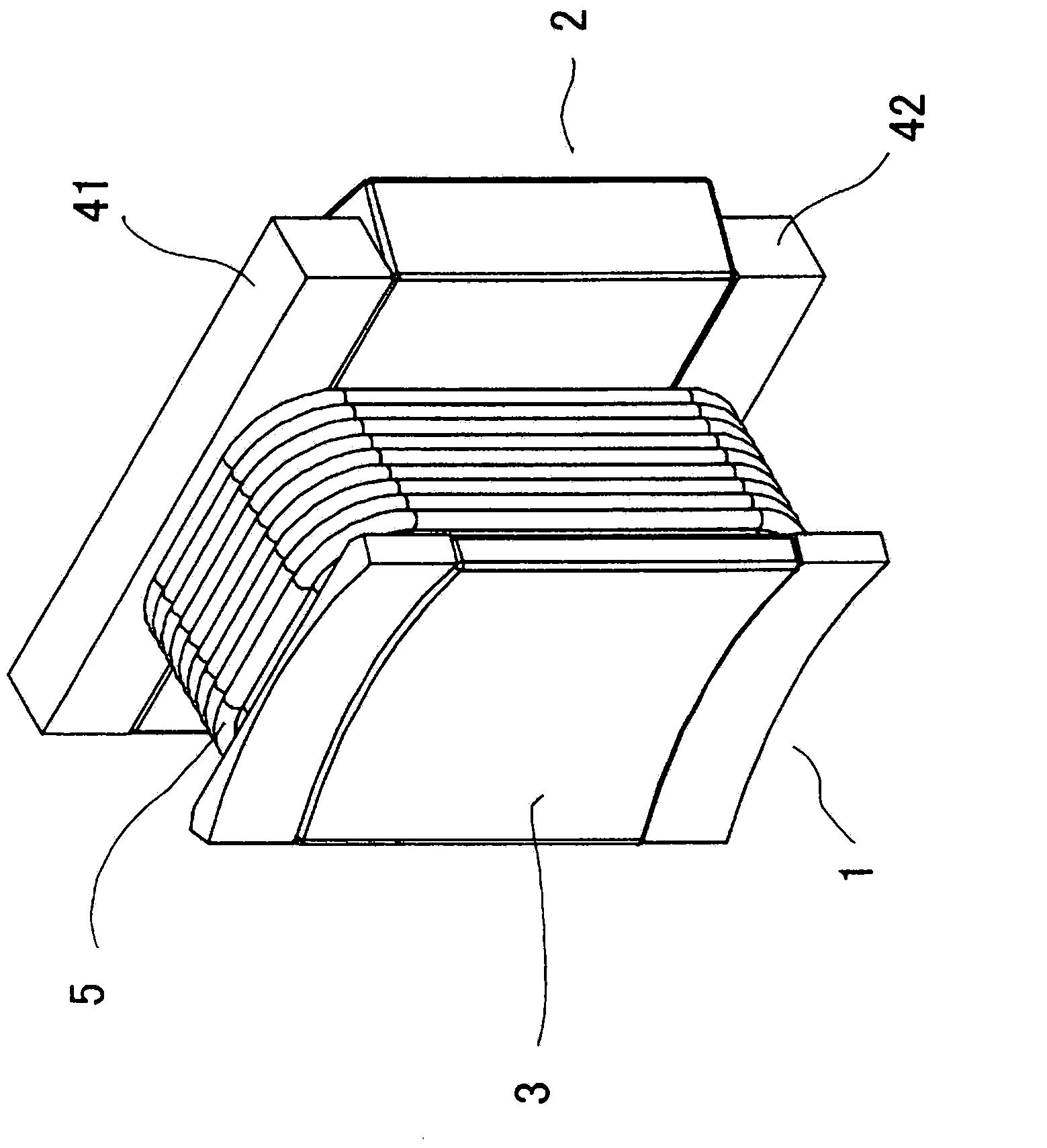
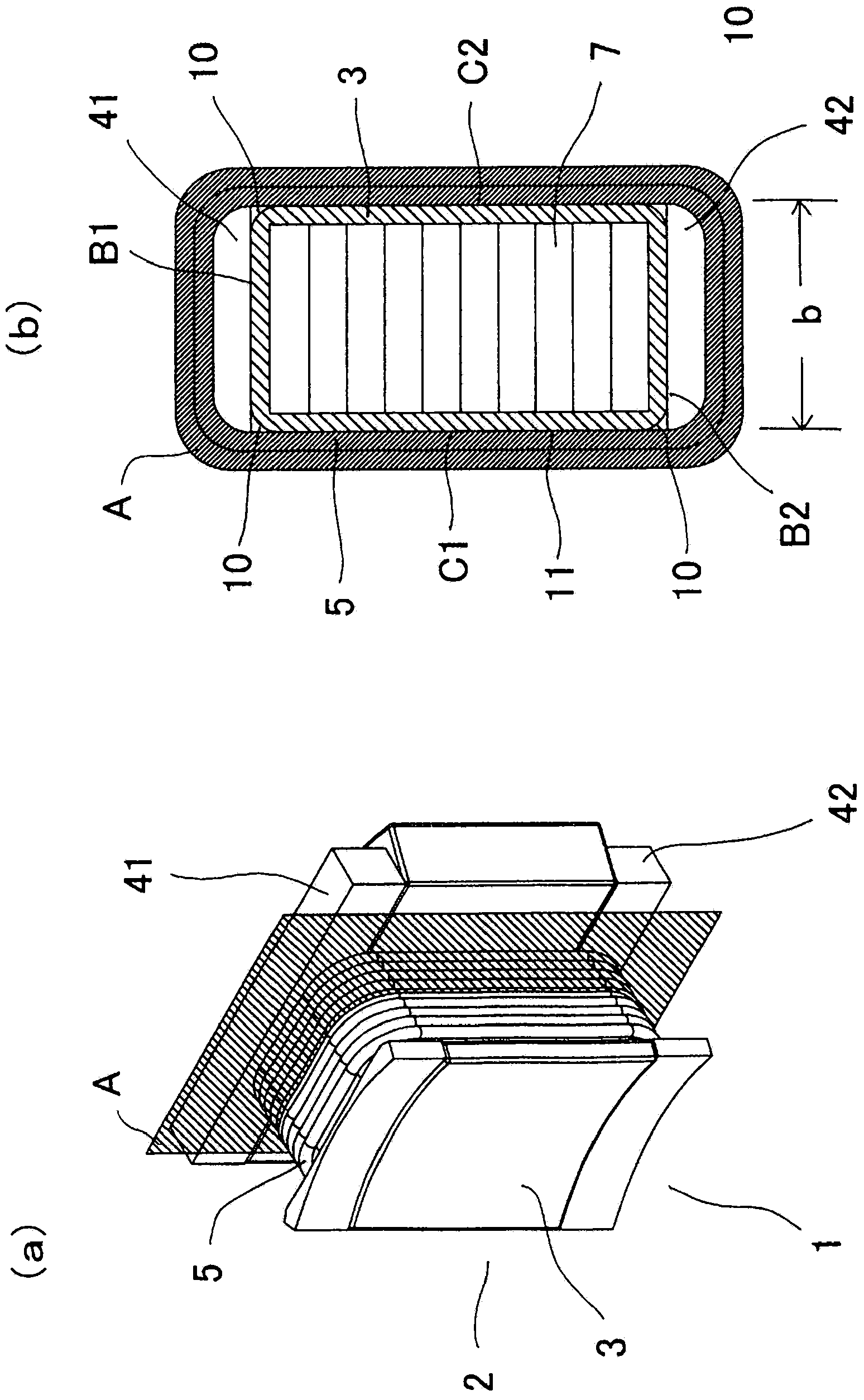
[0038] figure 1 It is a perspective view showing the stator magnetic pole portion in the stator of the rotating electrical machine according to Embodiment 1 of the present invention. figure 1Among them, the stator magnetic pole portion 1 constituting the stator of a rotating electric machine such as a motor includes a stator core 2 having a coating film 3 formed by applying an insulating paint coating process on the surface of a laminated core material. The core sheet laminate is formed by stacking a plurality of core sheets made of metal; the first bobbin 41 made of an insulator is mounted on one end surface of the stator core 2 which is the first surface in the stacking direction of the core sheets; a second bobbin 42 made of an insulating material, which is fitted on the other end face of the stator core 2 which is the second face in the stacking direction of the core sheets; and through the first bobbin 41 and the second bobbin 42 The stator coil 5 is formed by winding a ...

Embodiment approach 2

[0059] Figure 7 It is a perspective view showing the stator magnetic pole portion in the stator of the rotating electric machine according to Embodiment 2 of the present invention. Figure 7 Among them, a stator magnetic pole portion 1 a constituting a stator of a rotating electric machine such as a motor includes a stator core 2 a and a stator coil 5 assembled by winding a conductive wire around a tooth portion 9 a of the stator core 2 a. The stator core 2a is equipped with a first bobbin 42a and a second bobbin 42a respectively at both ends of a chip sheet laminate 6a formed by laminating a predetermined number of chip sheets. The core sheet laminate 6a, the first bobbin 42a, and the second bobbin 42a are integrally coated with insulating paint to form the stator core 16a. The stator coil 5 is formed by winding conductive wires around the tooth portions 9a of the stator core 2a configured in this way.

[0060]In addition, the first bobbin 41 and the second bobbin 42 may b...

Embodiment approach 3

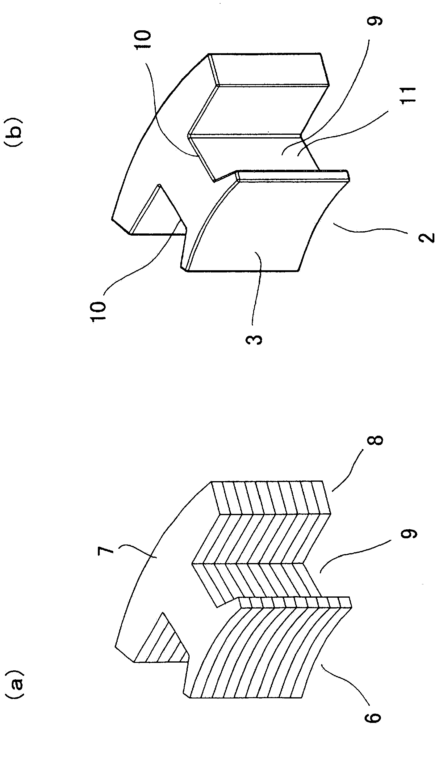
[0071] Figure 10 is a perspective view showing a core sheet in a stator of a rotating electrical machine according to Embodiment 3 of the present invention, Figure 11 It is a perspective view showing the stator magnetic poles in the stator of the rotating electric machine according to Embodiment 3 of the present invention. In the aforementioned first embodiment, the stator core stack 6 is constituted by using the substantially T-shaped core material 7 having the yoke 8 and the teeth 9 protruding from the yoke 8. However, in the third embodiment, as Figure 10 As shown, the stator core laminated body 6b may be constituted by using a core sheet 7b having a plurality of yoke portions 8b connected via bent portions 17 and a plurality of teeth portions 9b protruding substantially perpendicularly from each yoke portion 8b.

[0072] Such as Figure 11 As shown, the stator core 2b is produced by applying a coating film 3b made of insulating paint to the entire surface of a core sh...


PUM


Abstract

[Problem] To provide a stator for a rotating electrical machine which is capable of ensuring that the insulation properties at the edge of a stator coil are equal to or greater than those of the flat section of the stator coil; and a method for producing the stator. [Solution] This stator for a rotating electrical machine is provided with: a core sheet laminated body constituted by laminating a plurality of core sheets comprising a metal; a coating film comprising an insulation paint that has been applied to the surface of the core sheet laminated body; a stator coil comprising a conductive wire wound around the core sheet laminated body with the coating film there between; and a bobbin made of an insulating material, which is inserted between the coating film and the stator coil, and which either prevents the conductive wire of the stator coil from making contact with the coating film applied to the edge of the core sheet laminated body, or alleviates the pressure due to the contact.

Description

technical field [0001] The present invention relates to a stator of a rotating electrical machine including a core sheet laminate to which a coating film composed of an insulating paint is applied and a lead wire wound on the core sheet laminate, and a manufacturing method thereof. composed of stator coils. Background technique [0002] Conventionally, in stators that are components of rotating electric machines such as electric motors, in order to electrically insulate the stator cores from the wires wound on the stator cores, insulating coatings have been applied to the stator cores (see, for example, Patent Document 1). In the stator of such a conventional rotating electrical machine, methods such as electrodeposition coating, electrostatic coating, or spray coating can be cited as methods of applying insulating coating treatment to the stator core. However, in either method , Compared with the film thickness of the coating film applied on the flat part of the stator co...

Claims


Application Information

Patent Timeline
Patent Type & Authority Applications(China)
IPC IPC(8): H02K3/34
CPCH02K1/08H02K3/345H02K3/522H02K1/148H02K15/10H02K2203/12Y10T29/49009H02K3/34
Inventor 汤谷政洋司城大辅秋田裕之长谷川治之青海豪则小牧亮子
Owner MITSUBISHI ELECTRIC CORP
Why Eureka
Try Eureka