Antenna switch circuit and wireless terminal device

A technology for antenna switching and wireless terminals, applied in antennas, electrical components, transmission systems, etc., can solve problems affecting wireless communication, communication quality degradation, and failure to send and receive radio frequency signals normally, so as to avoid the impact

Active Publication Date: 2013-11-06
HUAWEI DEVICE CO LTD
View PDF2 Cites 32 Cited by
  • Summary
  • Abstract
  • Description
  • Claims
  • Application Information

AI Technical Summary

Problems solved by technology

When the RF connector is loose or falls off, the communication quality will be severely degraded, an

Method used


Image

  • Antenna switch circuit and wireless terminal device
  • Antenna switch circuit and wireless terminal device
  • Antenna switch circuit and wireless terminal device

Examples


Embodiment 1

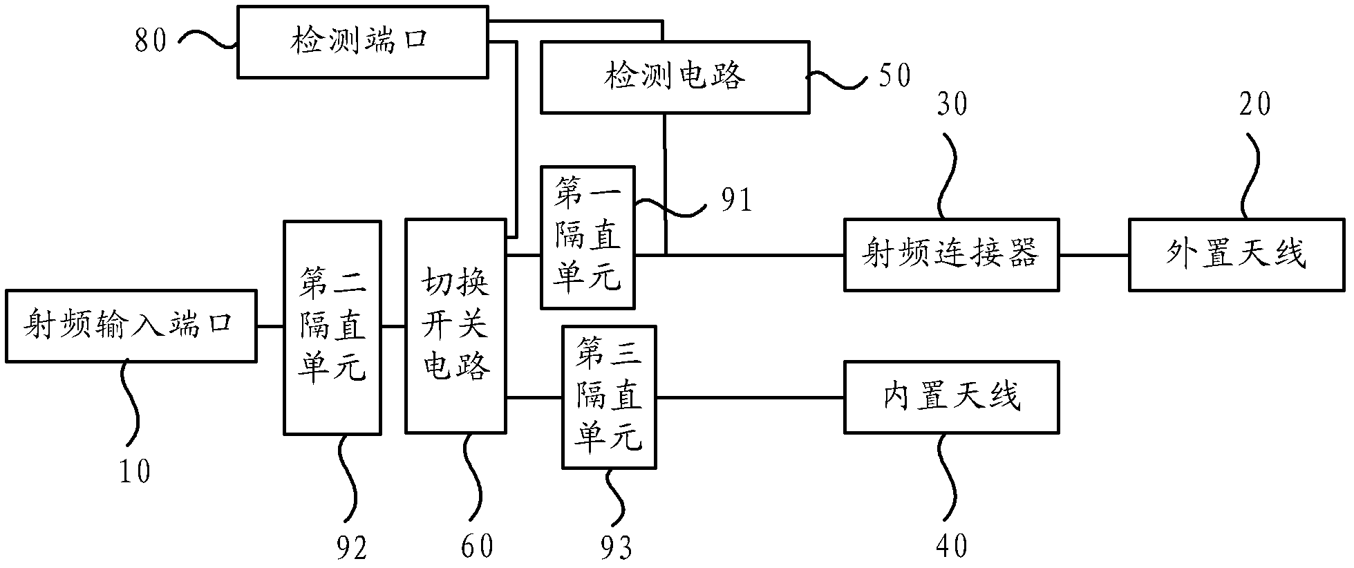
[0029] figure 1 It is a schematic structural diagram of an antenna switching circuit provided in Embodiment 1 of the present invention, and the antenna switching circuit is applicable to various wireless communication devices, such as wireless terminal devices such as mobile phones and power gateways.

[0030] The antenna switching circuit of this embodiment includes a radio frequency input port 10 for inputting a radio frequency signal, a detection port 80, a radio frequency connector 30 and a built-in antenna 40 for connecting an external antenna 20, and the external antenna 20 is connected to the radio frequency connector 30 to form a radio frequency channel.

[0031] Generally, the external antenna 20 can be detachably connected to the radio frequency connector 30, especially the external antenna is connected to the radio frequency connector 30, for example, plugged into the radio frequency connector 30 through a connector. Alternatively, the external antenna 20 can also ...

Embodiment 2

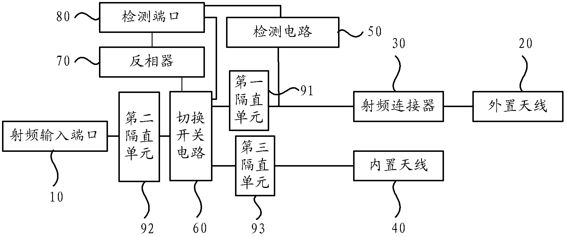
[0039] figure 2 It is a schematic structural diagram of another antenna switching circuit provided by Embodiment 2 of the present invention. This embodiment is similar to the first embodiment, the difference lies in the structure for controlling the operation of the switching circuit.

[0040]The antenna switching circuit provided in this embodiment includes a radio frequency input port 10 , a detection port 80 , a built-in antenna 40 , and a radio frequency connector 30 . The switching circuit also includes a detection circuit 50 , an inverter 70 and a switch circuit 60 . The detection circuit 50 is used to form a DC detection loop when the RF connector 30 is connected to the external antenna 20 to form a radio frequency channel, so that the detection port 80 obtains the DC voltage change in the RF channel in the DC detection loop; the input terminal of the inverter 70 Connect the detection port 80; the switch circuit 60 includes an input terminal connected to the radio fre...

Embodiment 3

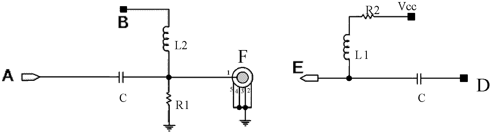
[0048] image 3 The structure schematic diagram of the antenna switching circuit provided by Embodiment 3 of the present invention, this embodiment may provide a preferred implementation of the detection circuit based on the above-mentioned embodiments, for the sake of clarity, the switching circuit is not shown.

[0049] In this implementation, the RF channel between the RF connector and the RF input port is connected to the ground wire through a voltage divider unit, which is used to form a DC detection circuit with the pull-up voltage connected to the external antenna when the RF connector is connected to the external antenna .

[0050] In this example, if image 3 As shown, the external antenna D is connected to the radio frequency connector F through the connector E; the number of AC isolation units is two, which are recorded as the first AC isolation inductance L1 and the second AC isolation inductance L2 in this embodiment; the pull-up voltage The port Vcc is connecte...


PUM


Abstract

The invention provides an antenna switch circuit and wireless terminal device. The device includes a radio-frequency input port, a detection port, an internal antenna and a radio-frequency connector. The device also includes a detection circuit, which is formed a DC detection circuit during forming a radio-frequency channel in the radio-frequency connector to connect the internal antenna, such that the detection port acquires a DC voltage change in the radio-frequency channel of the DC detection circuit; a switch circuit, which includes an input port connecting the radio-frequency input port, a control terminal connecting the detection port connection, and two input ports connecting the radio-frequency connector and the internal antenna respectively. The switch circuit according to the detection port acquires the DC voltage change to switch a connected relation of the input port and two output ports. The invention by a DC characteristics of the external antenna, though the detection circuit and the switch circuit is to automatically switch and connect between the internal antenna and the external antenna, to ensure an uninterrupted communication.

Description

technical field [0001] Embodiments of the present invention relate to wireless communication technologies, and in particular to an antenna switching circuit and a wireless terminal device. Background technique [0002] Installing an antenna on a wireless communication device is the basic structure for realizing wireless communication, and the external antenna is generally connected to the internal components of the wireless communication device through a radio frequency connector. Many wireless communication devices, especially wireless terminal equipment, use RF connectors to transmit RF signals between internal devices and external antennas. [0003] However, there are some defects in the above-mentioned radio frequency antenna connection structure. The radio frequency connector is often used in scenarios where no one is watching or inside the casing, such as power communication wireless communication equipment and the like. When the RF connector is loose or falls off, th...

Claims


Application Information

Patent Timeline
IPC IPC(8): H04B1/38
CPCH01Q15/00H04B1/00H01Q3/24
Inventor 彭勇景丰华
Owner HUAWEI DEVICE CO LTD
Why Eureka
Try Eureka