
A kind of impeller type aerator

An aerator and impeller technology, applied in fish farming, application, animal husbandry, etc., can solve the problems of limited plastic strength, easy rust process, easy damage, etc., to achieve no welding, reliable and firm connection, power matching Effect

Active Publication Date: 2016-08-03
吴为国
View PDF10 Cites 0 Cited by
  • Summary
  • Abstract
  • Description
  • Claims
  • Application Information

AI Technical Summary

Problems solved by technology

One end of the support rod of the usual impeller type aerator is welded with a flange and the other end is welded with a floating ball fixing ring made of iron sheet. After welding, it is easy to rust and the process is complicated. There are also brackets with plastic fixing rings that do not need to be welded, such as Patent: ZL200620008985.3, but when this kind of aerator is in use, the user hangs the rope that fixes the position of the aerator on the plastic fixing ring or plastic floating ball, and it is easy to be damaged due to the limited strength of the plastic

Method used


Image

  • A kind of impeller type aerator
  • A kind of impeller type aerator
  • A kind of impeller type aerator

Examples


Embodiment Construction

[0047] The present invention will be further described below with specific embodiment, see Figure 1-26 :

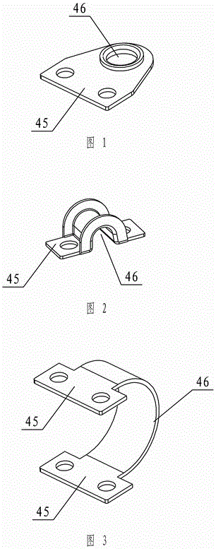
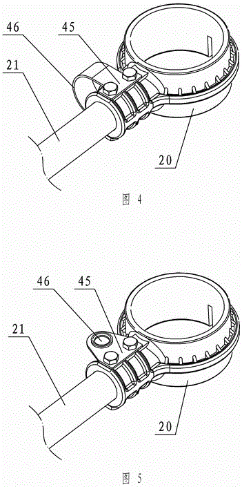
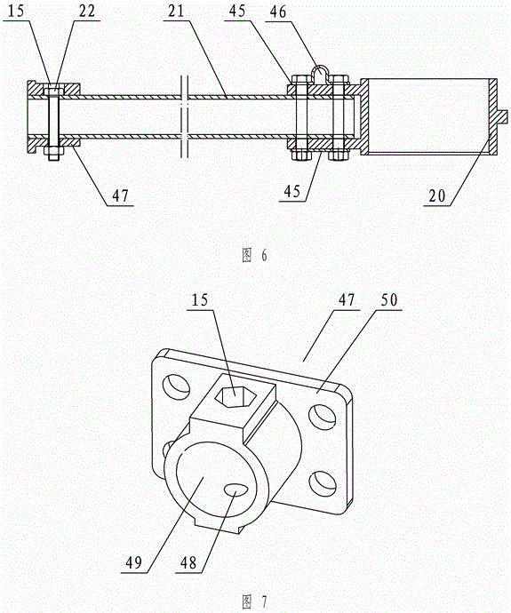
[0048] An impeller type aerator, including a motor 27, a reduction box, an impeller, a support rod 21, and a floating body 19. The motor 27 is vertically installed on the reduction box, and the decelerated output shaft 10 protrudes downwards, with a flange 44 at the end It is connected with the fixed seat 33 of the impeller, and there are three substantially evenly distributed connection positions 25 on the outside of the reduction box, and the support rod 21 is fixed on the connection position 25. The connecting seat 47 has an inner hole 49 matched with the steel pipe, and the side has a positioning hole intersecting with the inner hole 49. One side of the positioning hole is a hexagonal through hole 15, and the other side is a round through hole 48. The hexagonal head of the hexagonal bolt enters the hexagonal through hole. Holes 15, hex bolts 22 fasten the connection s...


PUM


Abstract

The invention relates to an impeller aerator, which comprises a motor, a reduction box, an impeller, a support rod, and a floating body, wherein the motor is vertically arranged on the reduction box; a decelerated output shaft is stretched out downwards; a flange is arranged on an end part of the output shaft and is connected with a fixed seat of the impeller; three basically uniformly distributed joints are arranged on the outer side of the reduction box; the support rod is fixed on the joints; a connecting seat is provided with an inner hole matched with a steel pipe; a locating hole intersected with the inner hole is arranged on a side face of the connecting seat; a hexagonal through hole is arranged on one side of the locating hole; a circular through hole is arranged on the other side of the locating hole; a hexagon head of a hexagon bolt enters into the hexagonal through hole; the connecting seat is fastened with the steel pipe through the hexagon bolt; a fixed ring I is arranged on the other end of the steel pipe; the fixed ring I is fastened with the steel pipe through base plates with two holes and two bolts; at least one base plate with two holes is provided with a fixing ring II; the support rod is fixed on the joints through the flange of the connecting seat; the floating body is fixed in the fixed ring I; a rope for fixing the aerator is fixed in the fixing ring II and is hung on a metal fixing ring; and the plastic fixing ring I and the floating body are not stressed, so that the connection is reliable and firm.

Description

technical field [0001] The invention relates to an aerator, in particular to an impeller type aerator, which belongs to fish farming machinery. Background technique [0002] The aerator is a life-saving and stimulating equipment for fish and shrimp in aquaculture. The existing mechanical aerators mainly include three types: water wheel type, impeller type and water spray type. Among them, the impeller type aerator is the most widely used, and the supporting device of the impeller type aerator belongs to the impeller type aerator. a component of . One end of the support rod of the usual impeller type aerator is welded with a flange and the other end is welded with a floating ball fixing ring made of iron sheet. After welding, it is easy to rust and the process is complicated. There are also brackets with plastic fixing rings that do not need to be welded, such as Patent: ZL200620008985.3, but when this aerator is in use, the user hangs the rope that fixes the position of th...

Claims


Application Information

Patent Timeline
Patent Type & Authority Patents(China)
IPC IPC(8): A01K63/04
Inventor 吴为国
Owner 吴为国
Learn More