Quenching pressing die fixture

A tooling and die technology, applied in quenching devices, manufacturing tools, heat treatment equipment and other directions, can solve the problems of large deformation, scrap, low product qualification rate, etc., to control deformation, ensure hardenability, and improve the qualification rate. Effect

Active Publication Date: 2013-11-13
四川神鸼精工科技有限公司
View PDF7 Cites 12 Cited by
  • Summary
  • Abstract
  • Description
  • Claims
  • Application Information

AI Technical Summary

Problems solved by technology

[0002] At present, when the shaft sleeve parts are quenched, due to their relatively thin wall thickness, there is a large amount of deformation, which seriously affects the product quality and even leads to scrapping; the existing quenching die tooling is only for the upper and lower ends of the workpiece. Pressing and quenching, the radial deformation is still uncontrollable, and the qualified rate of the product is low

Method used


Image

  • Quenching pressing die fixture
  • Quenching pressing die fixture
  • Quenching pressing die fixture

Examples


Embodiment Construction

[0013] The present invention will be described in further detail below in conjunction with the accompanying drawings.

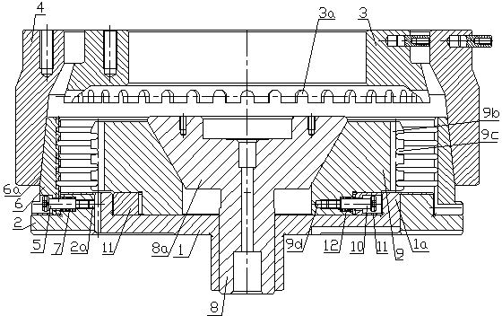
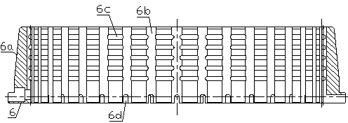
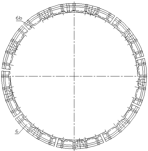
[0014] Such as figure 1 , figure 2 , image 3 As shown, the quenching die tooling includes a fixed tray 1, a backing plate 2 placed outside the fixed tray, an inner pressure ring 3, and an outer pressure ring 4 located outside the inner pressure ring. The lower end of the inner pressure ring 3 is provided with several A radial liquid tank 3a, the lower end of the outer pressure ring 4 is provided with a tapered hole with a large bottom and a small top, and three radial stepped holes 2a are provided on the backing plate 2, and a screw 5 is threaded in each stepped hole 2a , a supporting ring 6 is slidably mounted on the screws 5 outside the stepped holes 2a, and the screws 5 in the stepped holes 2a are covered with an external return spring 7, and the outer wall of the supporting ring 6 is provided with a lower part that matches the tapered hole of the oute...


PUM


Abstract

The invention discloses a quenching pressing die fixture which comprises a fixed tray, base plates, inner pressing rings and outer pressing rings, wherein conical holes with large lower parts and small upper parts are formed in the lower ends of the outer pressing rings; radial step holes are formed in the base plates; a screw is connected to each step hole; a supporting ring is arranged on each screw in a sliding manner; outer resetting springs are sleeved on the screws; conical surfaces with large lower parts and small upper parts are arranged on the outer walls of the supporting rings; a plurality of axial slots and a plurality of radial slots are formed in the inner walls of the supporting rings; a center hole and convex rings are arranged on the fixed tray; an expanding mandrel penetrates through the center hole and is provided with a cone with a large upper part and a small lower part; a plurality of expanding blocks are arranged around the cone on the fixed tray in a sliding manner; a conical surface matched with the cone is arranged on the inner wall of each expanding block; a plurality of axial slots and a plurality of radial slots are formed in the outer wall of each expanding block; each expanding block is provided with a radial step hole; a connection screw is connected with each step hole; inner resetting springs positioned between the convex rings and the corresponding expanding blocks are sleeved on the connection screws. The quenching pressing die fixture can effectively control the deformation of a workpiece in various directions and guarantee the hardenability, so that the yield of a product is greatly improved.

Description

technical field [0001] The invention relates to a quenching die tooling, in particular to a quenching die tooling for shaft sleeve parts. Background technique [0002] At present, when the shaft sleeve parts are quenched, due to their relatively thin wall thickness, there is a large amount of deformation, which seriously affects the product quality and even leads to scrapping; the existing quenching die tooling is only for the upper and lower ends of the workpiece. Pressing and quenching, the radial deformation is still uncontrollable, and the qualified rate of the product is low. Contents of the invention [0003] The object of the present invention is to provide a quenching die tooling for the above-mentioned shortcomings in the prior art, which can effectively control the deformation of workpieces in all directions, ensure hardenability, and greatly improve the qualified rate of products. [0004] In order to achieve the above object, a quenching die tooling of the...

Claims


Application Information

Patent Timeline
Patent Type & Authority Applications(China)
IPC IPC(8): C21D1/673
Inventor 付国祥
Owner 四川神鸼精工科技有限公司
Why Eureka
Try Eureka