Testing system for simulating hydraulic fracture of concrete members under high water pressure

A technology of hydraulic splitting and test system, applied in the field of test system, can solve the problems of unable to fully simulate the double hydraulic effect, unable to fully reflect the hydraulic splitting of concrete members under high water pressure, and difficult to test.

Active Publication Date: 2013-11-13
HOHAI UNIV
View PDF4 Cites 27 Cited by
  • Summary
  • Abstract
  • Description
  • Claims
  • Application Information

AI Technical Summary

Problems solved by technology

[0002] Cracks are the main response to the aging and disease of mass concrete structures. The problem of hydraulic splitting caused by high water pressure has always been a basic topic in the field of hydraulic engineering research. Due to the difficulty of concrete fracture tests under the action of water pressure and complicated devices, previous experimental studies Due to the limitations of model materials, manufacturing methods, and measurement techniques, the test uses mechanical pressure to simulate water pressure. This method cannot fully simulate the dual hydraulic effects of high-pressure water in cracks. The defect of the split test research is that there is no in-depth study on the crack formation process and the expansion of the crack after formation, such as crack width, concrete strain, and water pressure changes during the concrete cracking process.
Therefore, such tests cannot fully reflect the characteristics of hydraulic splitting of concrete members under high water pressure.

Method used


Image

  • Testing system for simulating hydraulic fracture of concrete members under high water pressure
  • Testing system for simulating hydraulic fracture of concrete members under high water pressure
  • Testing system for simulating hydraulic fracture of concrete members under high water pressure

Examples


specific Embodiment approach

[0029] Now, the technical solution of the present invention is further explained in conjunction with the specific embodiments.

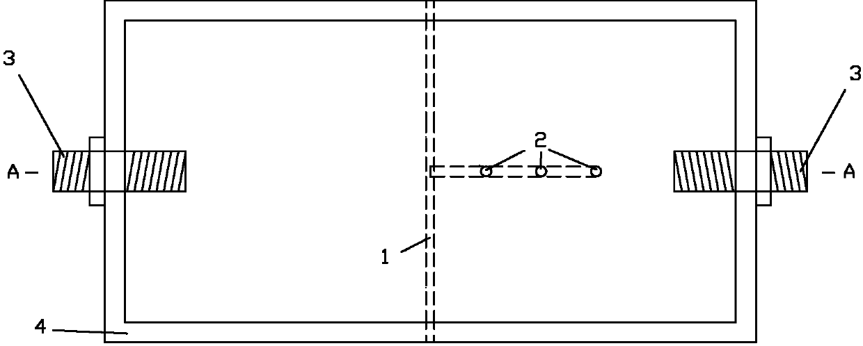
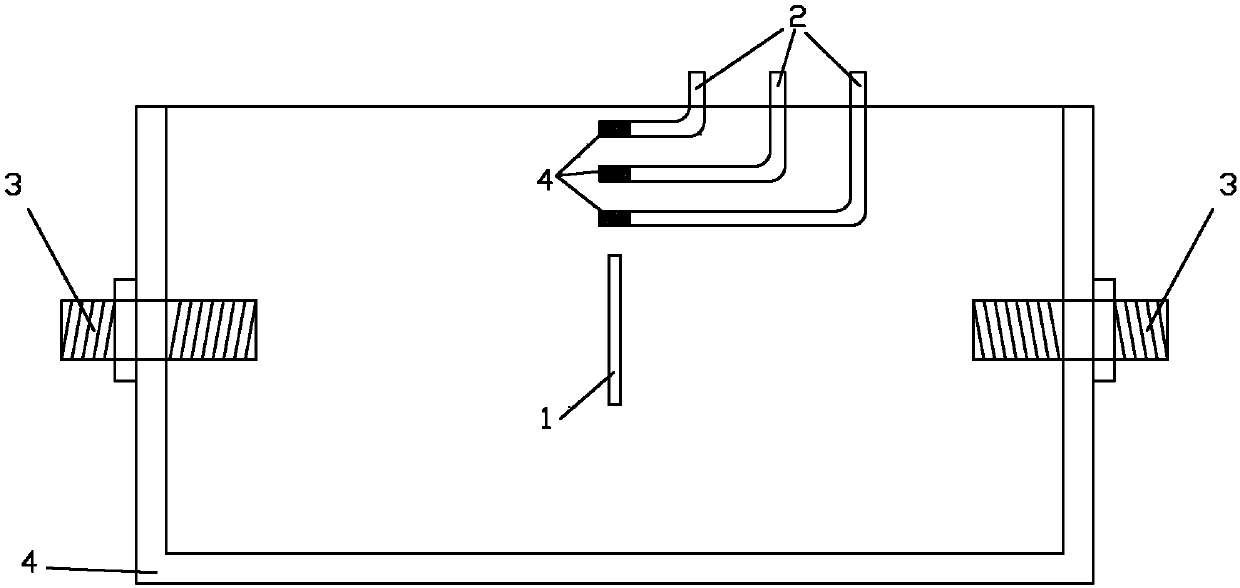
[0030] 1) Fabrication of the pouring mold for the test piece: Before pouring, a through hole is vertically processed in the front and rear centers of the mold for inserting the steel sheet for simulating the initial crack 1. After 24 hours of pouring, the steel sheet is pulled out to form the simulated initial crack 1, and normal maintenance thereafter Wait for the test; three water pressure measuring elbows 2 are pre-embedded in the attached image 3 In the position shown, the elbow goes deep into the concrete, and the pipe wall around 10mm at the front end of the elbow is filled with small holes, and wrapped with a layer of permeable geotextile 16, so that the water pressure can be transmitted into the elbow without concrete pouring. Or block the hole on the pipe wall during the vibration process; the position of the elbow can be adjusted to measu...


PUM

PropertyMeasurementUnit
widthaaaaaaaaaa
lengthaaaaaaaaaa

Abstract

The invention discloses a testing system for simulating hydraulic fracture of concrete members under high water pressure. The system comprises a specimen mould system and a water-solid thermal coupling testing system, the specimen moulding system comprises a casting mould and a water-sealing clamp, a simulation initial crack, which vertically runs through the casting mould, is arranged on the center position of the casting mould, a water pressure measuring elbow pipe is horizontally arranged above the simulation initial crack, one end of the water pressure measuring elbow pipe is embedded into the casting mould in a position which is opposite to the simulation initial crack, and the other end of the water pressure measuring elbow pipe stretches out of the casting mould and is connected to the water-solid thermal coupling testing system. The defects that the concrete wedge fracture specimen cannot be sealed under high water pressure in the conventional fracture tests and important data such as fracture aperture, water pressure and water temperature during the test process cannot be measured when a cylinder concrete specimen is adopted in the tests are overcome, the water sealing problem of the hydraulic fracture tests under high water pressure is solved, data such as the change and strain of water pressure in the crack during the fracture process can be measured in real time, and the test system is closer to the real situation.

Description

Technical field [0001] The present invention involves a test system for simulating hydraulic splitting of concrete components under high water pressure, which is the field of test device. Background technique [0002] Cracks are the main reactions of the aging of large -volume concrete structures and lesions. The problem of hydraulic splitting caused by high water pressure has always been the basic topic of the research of the water conservancy engineering industry. Due to the difficulty of the difficulty of the concrete fracture test under the action of hydraulic pressure, the complicated device is complicated.Due to the restrictions of model materials, production methods, measurement techniques, etc., the test uses mechanical pressure to simulate water pressure. This method cannot completely simulate the dual hydraulic effects of high pressure water in the crack, or some scholars perform high pressure water under concrete test parts under the condition of stress stress conditio...

Claims


Application Information

Patent Timeline
Patent Type & Authority Applications(China)
IPC IPC(8): G01N3/12
Inventor 甘磊沈振中徐力群仲良王瑞焦延涛
Owner HOHAI UNIV
Why Eureka
Try Eureka