Infrared camera lens based on temperature change compensation and compensation method

A technology of temperature change and infrared lens, which is applied in the field of infrared lens, can solve the problems of increasing the overall structural size, difficulty in design and manufacture, unfavorable lens barrel transmission structure, etc., and achieve the effect of simple and optimal imaging effect

Active Publication Date: 2013-11-13
山东神戎电子股份有限公司
View PDF9 Cites 40 Cited by
  • Summary
  • Abstract
  • Description
  • Claims
  • Application Information

AI Technical Summary

Problems solved by technology

Due to the need to consider the relationship between structure, material and temperature-varying characteristics of the lens group, this type of structure makes its design and manufacture more difficult, and the additional compensation lens barrel will inevitably increase the overall structure size, which is not conducive to The setting of lens barrel transmission structure

Method used


Image

  • Infrared camera lens based on temperature change compensation and compensation method
  • Infrared camera lens based on temperature change compensation and compensation method
  • Infrared camera lens based on temperature change compensation and compensation method

Examples


Embodiment Construction

[0017] The present invention will be further described below in conjunction with the accompanying drawings and embodiments.

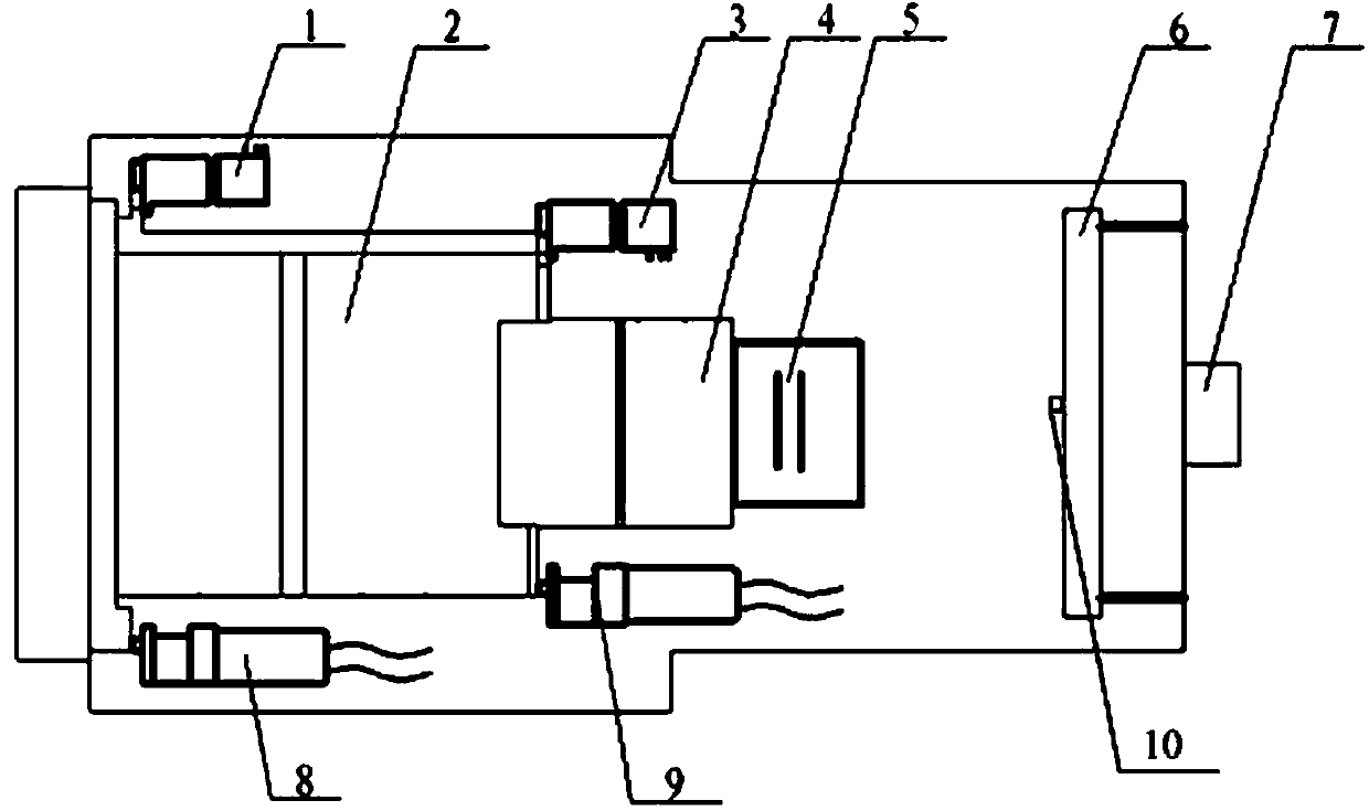
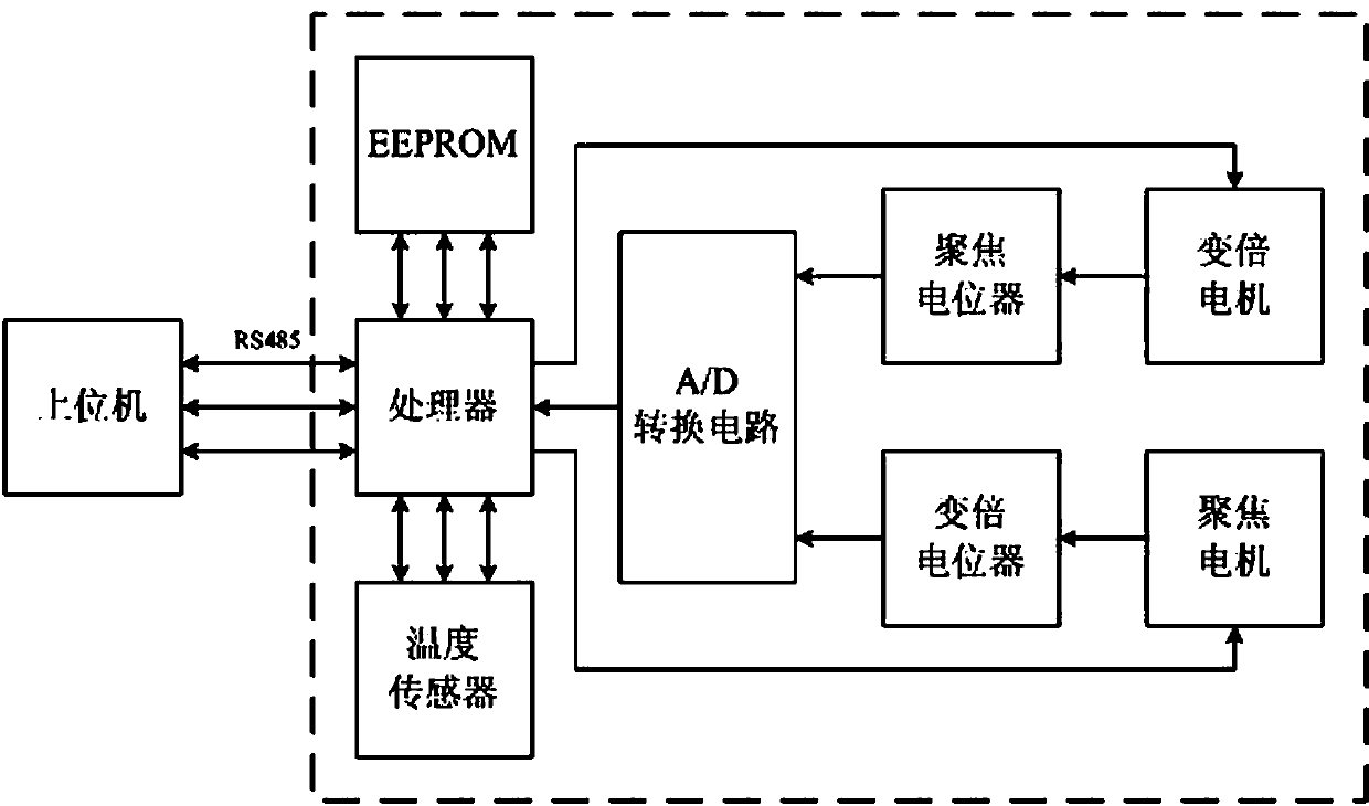
[0018] Such as figure 1 , figure 2 As shown, a schematic diagram of the internal structure and a schematic diagram of the circuit part of a zoom infrared thermal imager are respectively given. Please refer to the attached figure 1 As shown, the zoom infrared camera that intelligently compensates the lens position based on temperature changes is mainly composed of a zoom lens group 2, a focusing lens group 4, and a detector assembly 5 for infrared imaging, which are arranged front and rear on the optical axis. The zoom lens group 2 and the focusing lens group 4 are equipped with corresponding detection equipment, such as figure 1 The zoom potentiometer assembly 1 and the focus potentiometer assembly 3 shown in , correspondingly, the focus lens group 4 and the zoom lens group 2 are respectively equipped with a zoom motor assembly 8 and a focus motor a...


PUM


Abstract

The invention discloses an infrared camera lens based on temperature change compensation and a compensation method. When a temperature change exceeds a certain limit, a mathematical function of the relation between the focus lens group compensation capacity and the temperature difference is called to adjust the position of a focus lens group, the implementation is very simple, and an optimum imaging effect still can be effectively guaranteed to be realized after the temperature changes.

Description

technical field [0001] The invention relates to an infrared lens and a compensation method for eliminating or reducing the influence of temperature on the imaging of the infrared lens when the temperature changes. Background technique [0002] With the development of infrared thermal imaging technology, continuous zoom thermal imaging cameras have appeared, such as the continuous zoom uncooled thermal imaging camera disclosed in Chinese patent document CN101282428A, the operator can independently control the zooming of the thermal imaging camera at the background control terminal. Magnification and focus can not only realize a large-scale search, but also zoom in and identify specific targets, which is convenient for monitoring. [0003] However, since thermal imaging cameras are mostly used outdoors, especially in some border and sea defense lines, the temperature changes in the environment where they are located are relatively drastic. Limited by cost and technology, most...

Claims


Application Information

Patent Timeline
Patent Type & Authority Applications(China)
IPC IPC(8): G02B7/04G02B27/00G01J5/08
Inventor 于洋丁鉴彬姜河路瑜亮
Owner 山东神戎电子股份有限公司
Why Eureka
Try Eureka