
Touch panel

A technology of touch panel and touch area, which is applied in the fields of instruments, electrical digital data processing, input/output process of data processing, etc.

Inactive Publication Date: 2013-11-13
J TOUCH CORPORATION
View PDF5 Cites 12 Cited by
  • Summary
  • Abstract
  • Description
  • Claims
  • Application Information

AI Technical Summary

Problems solved by technology

[0004] In order to realize a borderless touch device, it is first necessary to try to hide the opaque metal lines, but for the existing technology, there is always a bottleneck that is difficult to break through

Method used


Image

  • Touch panel
  • Touch panel
  • Touch panel

Examples


Embodiment Construction

[0016] The above and other technical features and advantages of the present invention will be described in more detail below in conjunction with the accompanying drawings.

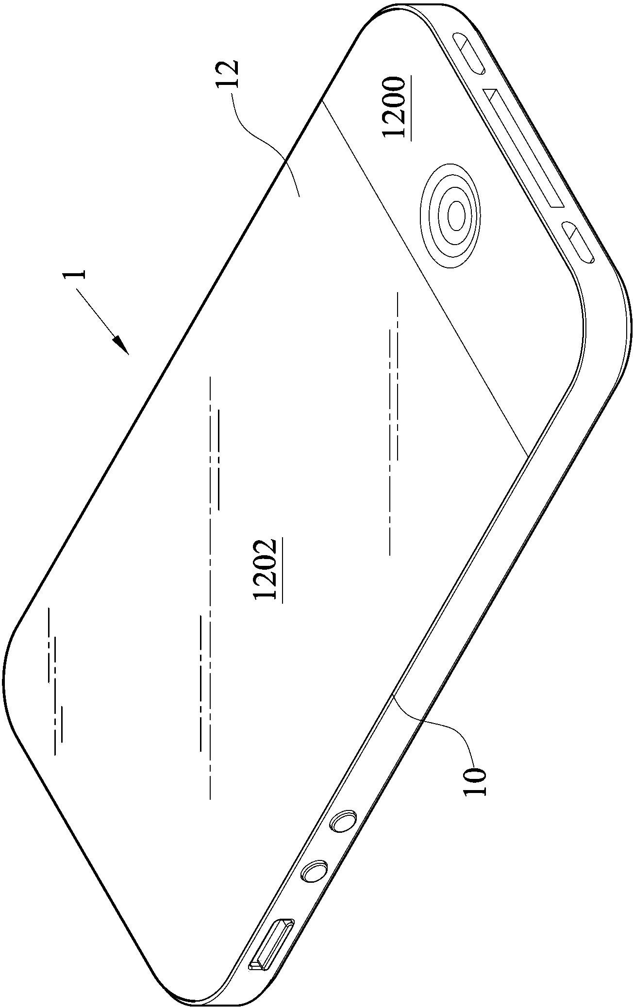
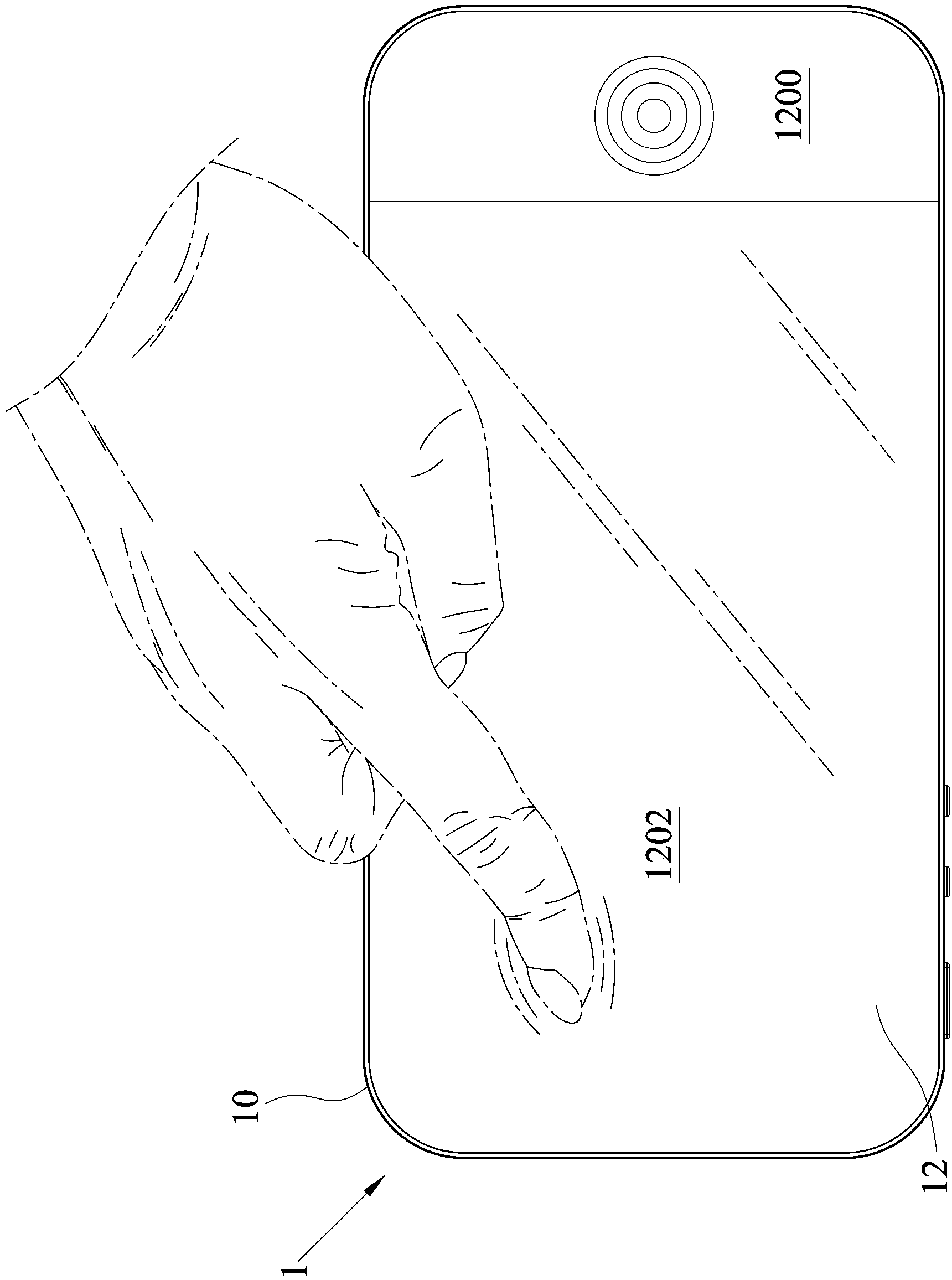
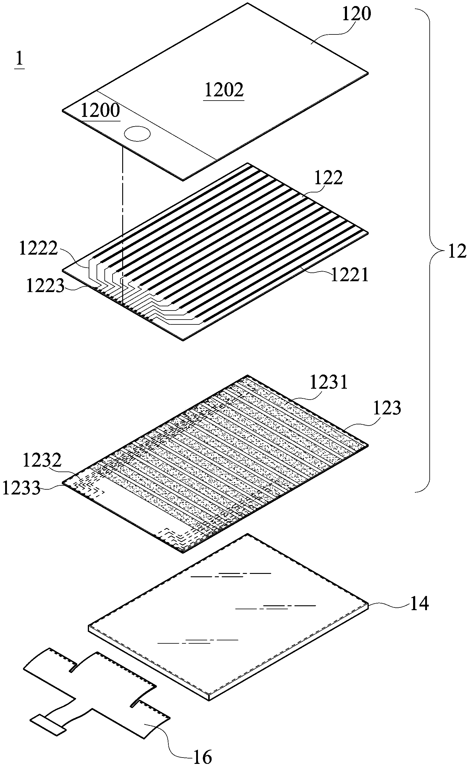
[0017] see Figure 1A and Figure 1B , is a schematic view of the appearance and a schematic view of the operation of a preferred embodiment of the present invention. As shown in the figure, the touch panel 12 of the present invention is used in an electronic device 1 . The electronic device 1 may be a portable electronic device such as a smart phone or a tablet computer, and has an outline 10 . The touch panel 12 includes a shielding area 1200 and a transparent touch area 1202, the shielding area 1200 is set on the surface of the electronic device 1, the transparent touch area 1202 is set adjacent to the shielding area 1200, and most of the transparent touch area 1202 is covered by the electronic device. 1 is surrounded by the contour line 10. Such as Figure 1B As shown, except for the shielding area ...


PUM


Abstract

The invention discloses a touch panel, which is used in an electronic device with a contour line. The touch panel comprises a shielding area and a transparent touch area, wherein the shielding area is arranged on the surface of the electronic device; and the transparent touch area is arranged adjacent to the shielding area, and most of the transparent touch area is surrounded by the contour line of the electronic device. According to the touch panel disclosed by the invention, a frameless design of the touch panel can be realized.

Description

technical field [0001] The invention relates to a touch panel, in particular to a frameless touch panel applied to a portable electronic device. Background technique [0002] With the development of science and technology, general consumer electronic products such as: mobile communication devices, digital cameras, digital music players (MP3), personal digital assistants (PDA), satellite navigation devices (GPS), etc., have generally used touch panels As its main operation interface, it is used for interactive input operations between users and electronic products, greatly improving the affinity between human and machine communication, and improving the operation efficiency during input. [0003] Currently, the touch devices on the market usually have a screen, which not only can display lively images, but also allows users to perform touch operations on the screen. However, in order to cover the metal lines inside the screen, a frame or an image layer (ICON) is usually coat...

Claims


Application Information

Patent Timeline
Patent Type & Authority Applications(China)
IPC IPC(8): G06F3/041
Inventor 叶裕洲
Owner J TOUCH CORPORATION
Learn More