
A concave-convex die-cutting molding die

A technology of forming molds and concave-convex molds, applied in decorative arts, metal processing, embossed decorative parts, etc., can solve problems such as affecting product die-cutting quality, increasing product rejection rate, and increasing production costs, and achieves improved graphics and texts. The effect of reducing height drop and saving cost

Active Publication Date: 2016-01-20
ZHEJIANG KAISHI LASER TECH CO LTD
View PDF4 Cites 0 Cited by
  • Summary
  • Abstract
  • Description
  • Claims
  • Application Information

AI Technical Summary

Problems solved by technology

[0003] The concave-convex and die-cutting of the traditional mold cannot be carried out at the same time, and must be divided into two processes. In the existing market, the concave-convex die-cut can be completed in a unified process. The distance between the embossed pattern and the crimped line must be greater than 5mm. If The distance between the pattern and the pressing line is less than 5mm. The existing concave-convex die-cutting one-time molding process will cause the paper to be easily twisted and damaged due to the height limitation between the punch and the bottom plate, and the blade will be damaged during the die-cutting process due to the high height. Deformation affects the quality of die-cutting products, and it is easy to produce fuzzing and bursting lines in the die-cutting process, resulting in increased product scrap rate, increased production costs, and decreased production efficiency

Method used


Image

  • A concave-convex die-cutting molding die

Examples


Embodiment Construction

[0012] In order to make the technical means, creative features, goals and effects achieved by the present invention easy to understand, the present invention will be further elaborated below in conjunction with illustrations and specific embodiments.

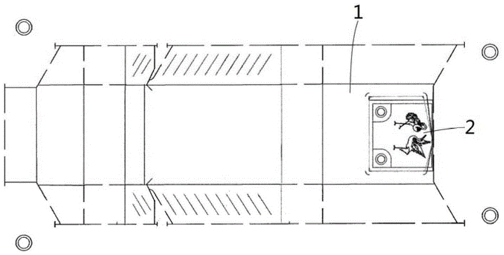
[0013] Such as figure 1 As shown, the concave-convex die-cutting one-time molding mold proposed by the present invention includes a base plate 1 and a convex plate 2, and the base plate 1 has a mounting groove, and the convex plate 2 is arranged on the base plate 1 through the mounting groove, and the bottom of the convex plate 2 is located in the mounting groove. , the top of which protrudes from the installation groove, and the engraving pattern of the convex formwork 2 is located on the top;

[0014] There is adhesive glue in the installation groove, and the bottom of the convex formwork 2 is fixed in the installation groove through the adhesive glue;

[0015] In one embodiment of the present invention, the depth of the inst...


PUM


Abstract

The invention provides a concave-convex die-cutting one-step forming die which comprises a base plate and a convex template, wherein an installation groove is formed in the base plate; the convex template is arranged on the base plate through the installation groove; the bottom of the convex template is located in the installation groove, the top of the convex template stretches out of the installation groove; carved patterns of the convex template are located at the top of the convex template; clamping grooves is formed in the periphery of the convex template; and the periphery of the convex template is connected with the base plate through the clamping grooves, so that the distance between the convex template and a knife edge is reduced, the die-cutting accuracy can be guaranteed, and the concave-convex effect of images and texts is more excellent. The die can avoid paper twist caused by height limitation and reduce the height difference, so that the die is more stable in a concave-convex die-cutting process, and the effect and the quality are more excellent; at the same time, a die-cutting blade is protected, and deformation is prevented, so that the cost is saved, and the working efficiency is improved; and the problem of distance restriction is solved, so that product requirements for accurate and precision packaging can be met, and the image-text fineness of a product is promoted.

Description

technical field [0001] The invention relates to a post-printing process packaging tool for paper products, in particular to a concave-convex die-cutting one-time forming mold. Background technique [0002] Embossing is an important process in the post-printing process of packaging. It is an embossing method that does not use printing ink. A set of concave and convex templates corresponding to the Yin and Yang of the graphic and text are used to place the substrate between them. Press out embossed embossed text by applying high pressure. This method is mostly used for post-press processing of printed matter and paper containers, such as trademarks, cigarette packs, cartons, New Year cards, bottle labels, etc., so that they can obtain a vivid and beautiful three-dimensional effect. Proper use of embossing technology can increase printing The layering of the pattern plays a finishing touch on the packaging products. [0003] The concave-convex and die-cutting of the tradition...

Claims


Application Information

Patent Timeline
Patent Type & Authority Patents(China)
IPC IPC(8): B44B5/02B26F1/44
Inventor 不公告发明人
Owner ZHEJIANG KAISHI LASER TECH CO LTD
Learn More