Satellite-borne phased-array receiving antenna testing system

A technology for receiving antennas and testing systems, applied in transmission systems, antenna radiation patterns, transmission monitoring, etc., can solve problems such as unintuitive display, long system construction period, and inability to perform rapid tests

Active Publication Date: 2013-11-20
SHANGHAI INST OF MICROSYSTEM & INFORMATION TECH CHINESE ACAD OF SCI +1
View PDF6 Cites 16 Cited by
  • Summary
  • Abstract
  • Description
  • Claims
  • Application Information

AI Technical Summary

Problems solved by technology

The disadvantages of the all-physical test system are: 1) It is impossible to test the beam radiation pattern of the spaceborne phased array antenna; 2) The display is not intuitive and expensive, and it is very inflexible, and the communication system cannot be changed according to the test needs; 3) System construction The cycle time is long, and rapid testing is not possible

Method used


Image

  • Satellite-borne phased-array receiving antenna testing system
  • Satellite-borne phased-array receiving antenna testing system
  • Satellite-borne phased-array receiving antenna testing system

Examples


Embodiment Construction

[0025] The specific implementation of the spaceborne phased array receiving antenna test system provided by the present invention will be described in detail below in conjunction with the accompanying drawings.

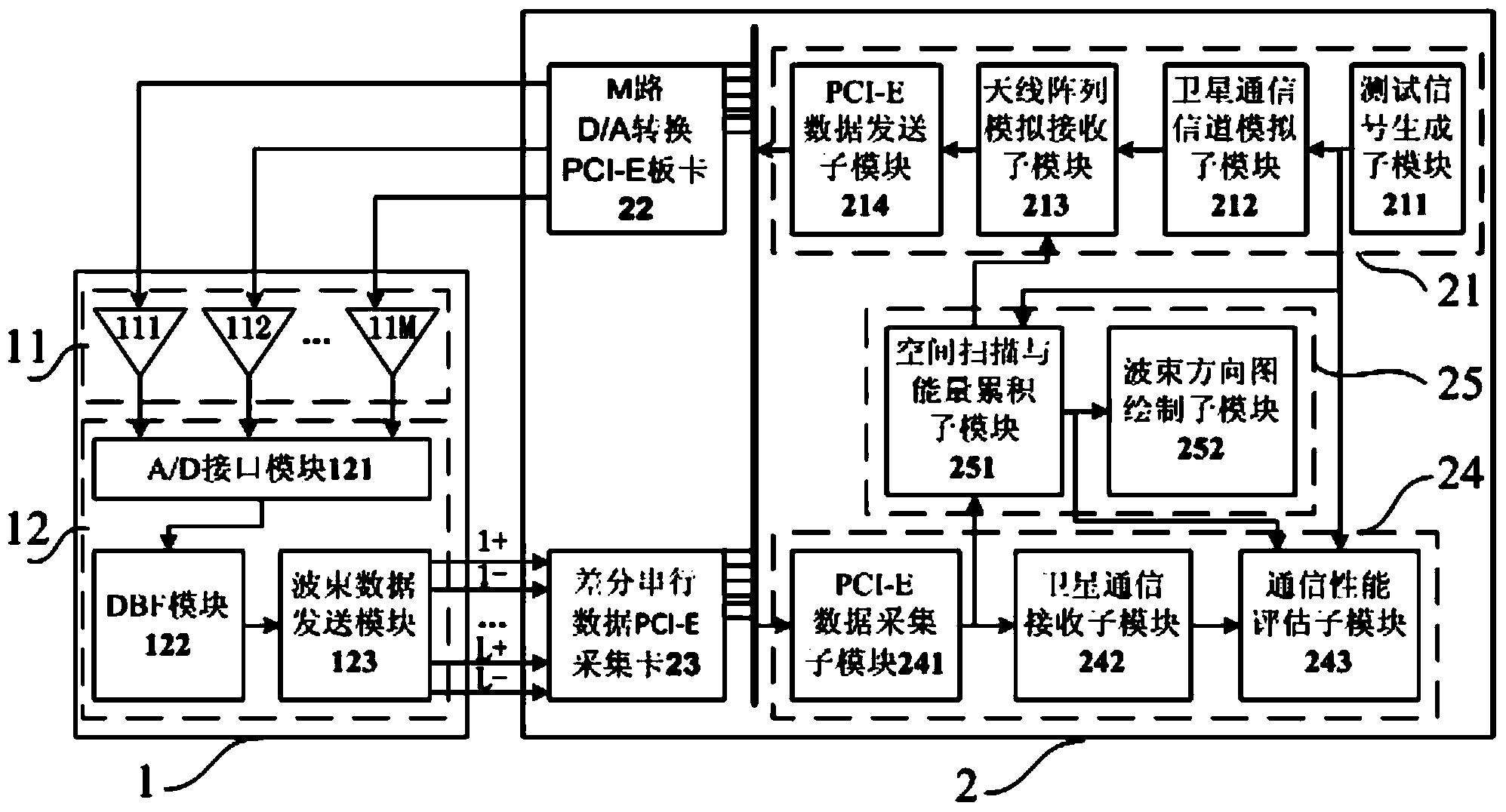
[0026] refer to figure 1 , a schematic diagram of the structure of the spaceborne phased array receiving antenna test system of the present invention, the system includes a spaceborne phased array receiving antenna DBF baseband physical stand-alone 1 and a half-physical test host computer 2. The main function of the DBF baseband physical stand-alone 1 of the space-borne phased array receiving antenna is to complete A / D sampling, convert multiple radio frequency channel signals into corresponding multiple digital signals; and then perform DBF processing on the digital signals sampled by A / D ; Finally, the data of multiple beams is transmitted to the hardware-in-the-loop test host computer 2 of the spaceborne phased array receiving antenna through a high-speed different...


PUM


Abstract

A satellite-borne phased-array receiving antenna testing system comprises the DBF (Digital Beam Forming) baseband physical stand-alone and the semi-physical testing upper computer of a satellite-borne phased-array receiving antenna; the DBF baseband physical stand-alone comprises an A / D converter group and a DBF baseband unit connected with the A / D converter group; the semi-physical testing upper computer comprises a test data transmission module, a multi-way D / A conversion PCI-E (Peripheral Component Interconnect Express) board card, a differential serial data PCI-E capture card, a test data receiving and processing module and a beam directional diagram calculating and drawing module; the test data transmission module is connected with the multi-way D / A conversion PCI-E board card; the differential serial data PCI-E capture card is connected with the DBF baseband unit; the test data receiving and processing module is respectively connected with the differential serial data PCI-E capture card, the beam directional diagram calculating and drawing module and the test data transmission module; the beam directional diagram calculating and drawing module is respectively connected with the test data receiving and processing module and the test data transmission module.

Description

technical field [0001] The invention relates to the technical field of aerospace electronic communication, in particular to a test system for a spaceborne phased array receiving antenna using half-in-the-loop testing. Background technique [0002] In the 1990s, multi-beam phased array antenna technology began to be used in communication satellites, which has the advantages of low loss and large-angle dynamic scanning, and is more representative such as the Globalstar and Iridium satellite systems in the United States. [0003] The basic idea of ​​beamforming in a multi-beam phased array antenna is to control the amplitude and phase of each feed point of the array antenna. Analog beamforming can be realized through the feed network at the radio frequency end, or digital beamforming can be realized at baseband or intermediate frequency through digital domain processing. In analog beamforming, once the beamforming scheme is determined, the beam shape, the intersection level of ...

Claims


Application Information

Patent Timeline
Patent Type & Authority Applications(China)
IPC IPC(8): G01R29/10H04B17/00H04B17/12
Inventor 宋海伟梁广龚文斌余金培王勇勇
Owner SHANGHAI INST OF MICROSYSTEM & INFORMATION TECH CHINESE ACAD OF SCI
Why Eureka
Try Eureka