Split-spoon change-over switch in on-load tap-changer

A transfer switch and on-load tapping technology, which is applied in the field of electromechanical manufacturing, can solve the problems of complex structure and low assembly efficiency of the high-low push-post transfer switch.

Active Publication Date: 2015-04-29
贵州长征电气有限公司
View PDF5 Cites 0 Cited by
  • Summary
  • Abstract
  • Description
  • Claims
  • Application Information

AI Technical Summary

Problems solved by technology

[0002] In the existing oil-immersed vacuum on-load tap-changer, it uses a high-low column changeover switch. The structure of the high-low column changeover switch is complicated. The center of the contact, the assembly efficiency is low

Method used


Image

  • Split-spoon change-over switch in on-load tap-changer
  • Split-spoon change-over switch in on-load tap-changer

Examples


Embodiment Construction

[0021] In view of the existing technical defects, the purpose of the patent of this invention is to provide a split transfer switch. During the operation of the transfer switch, due to the large distance between the static contacts, the static contact of the split transfer switch The head is not easy to be broken down, so that the reliability of the switch can be improved. Moreover, the invention has a simple and compact structure and is easy to assemble.

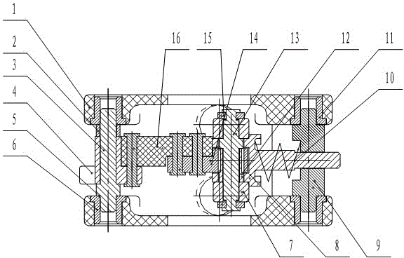
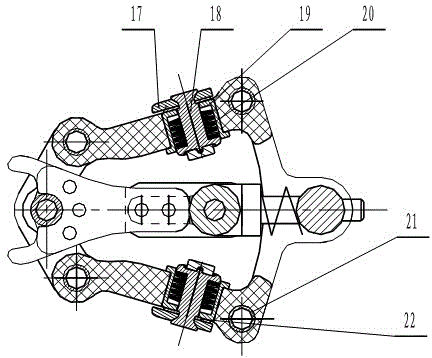
[0022] Such as figure 1 , figure 2 As shown, the split change-over switch in the on-load tap-changer, the change-over switch includes:

[0023] Box 1, the load-bearing installation part of the entire split transfer switch; the second bushing 19 is installed on the box 1; the disc spring 20 is installed between the static contact 18 and the second bushing 19; the third bushing 21 is located in the box 1 Cavity; bushing one 2, mounted on shaft one 3, to prevent shifting fork 4 from sliding up and down; shifting fork 4 and...


PUM


Abstract

The invention relates to a split-spoon change-over switch in an on-load tap-changer, which comprises boxes, liner bushings I, shafts I, shifting forks, adjusting shims and shaft sleeves I, wherein the boxes serve as bearing and mounting parts of the whole split-spoon change-over switch; shaft sleeves II are mounted on the boxes; belleville springs are mounted between fixed contacts and the shaft sleeves II; liner bushings III are positioned in the inner chambers of the boxes; the liner bushings I are mounted on the shafts I to prevent the shifting forks from sliding up and down; the shifting forks are tightened with supporting parts III together; the supporting parts III are tightened with supporting parts II together; the supporting parts II are sleeved on shaft III, and can rotate flexibly; the shafts I are mounted on the shaft sleeves I in the boxes; the shifting forks are mounted on the shafts I, and can rotate by winding along the shafts I; the adjusting shims are used for adjusting the clearances between the shafts I and the shifting forks; the shaft sleeves I are in tight fit with holes on the boxes, and fixed on the boxes. During the switch process of the split-spoon change-over switch, as the distances of the fixed contacts are larger, electric is not easy to discharge among the fixed contacts, and the reliability of the switch is enabled to be improved.

Description

technical field [0001] The invention belongs to the field of electromechanical manufacturing, and in particular relates to a split-type transfer switch for an oil-immersed vacuum on-load tap changer switch. Background technique [0002] In the existing oil-immersed vacuum on-load tap-changer, it uses a high-low column changeover switch. The structure of the high-low column changeover switch is complicated. The center of the contact, the assembly efficiency is low. Contents of the invention [0003] In order to overcome the above-mentioned defects, the technical problem to be solved by the present invention is to provide a split-type transfer switch for on-load tap changer changeover switch with simple structure and easy assembly. [0004] Split changer in on-load tap-changer: the change-over switch consists of: [0005] ——The box, the load-bearing installation part of the whole split transfer switch; the second shaft sleeve is installed on the box; the disc spring...

Claims


Application Information

Patent Timeline
Patent Type & Authority Patents(China)
IPC IPC(8): H01H33/66H01H1/56
Inventor 谢雅琪
Owner 贵州长征电气有限公司
Why Eureka
Try Eureka