
Connector with small housing

A technology for connectors and housings, applied in the field of connectors, which can solve the problems of low assembly operability of the connector 301 and easy falling off of the gasket 306, and achieve good assembly operability and prevent parts from falling off

Inactive Publication Date: 2013-11-20
YAZAKI CORP
View PDF3 Cites 7 Cited by
  • Summary
  • Abstract
  • Description
  • Claims
  • Application Information

AI Technical Summary

Problems solved by technology

That is, because the spacer 306 in the connector 301 is formed in a cylindrical shape so that its cross-sectional circle is partially cut off, and therefore the spacer 306 easily falls off when each component is assembled to the housing 303, the connector 301 There is a problem that assembly workability is low

Method used


Image

  • Connector with small housing
  • Connector with small housing
  • Connector with small housing

Examples


Embodiment Construction

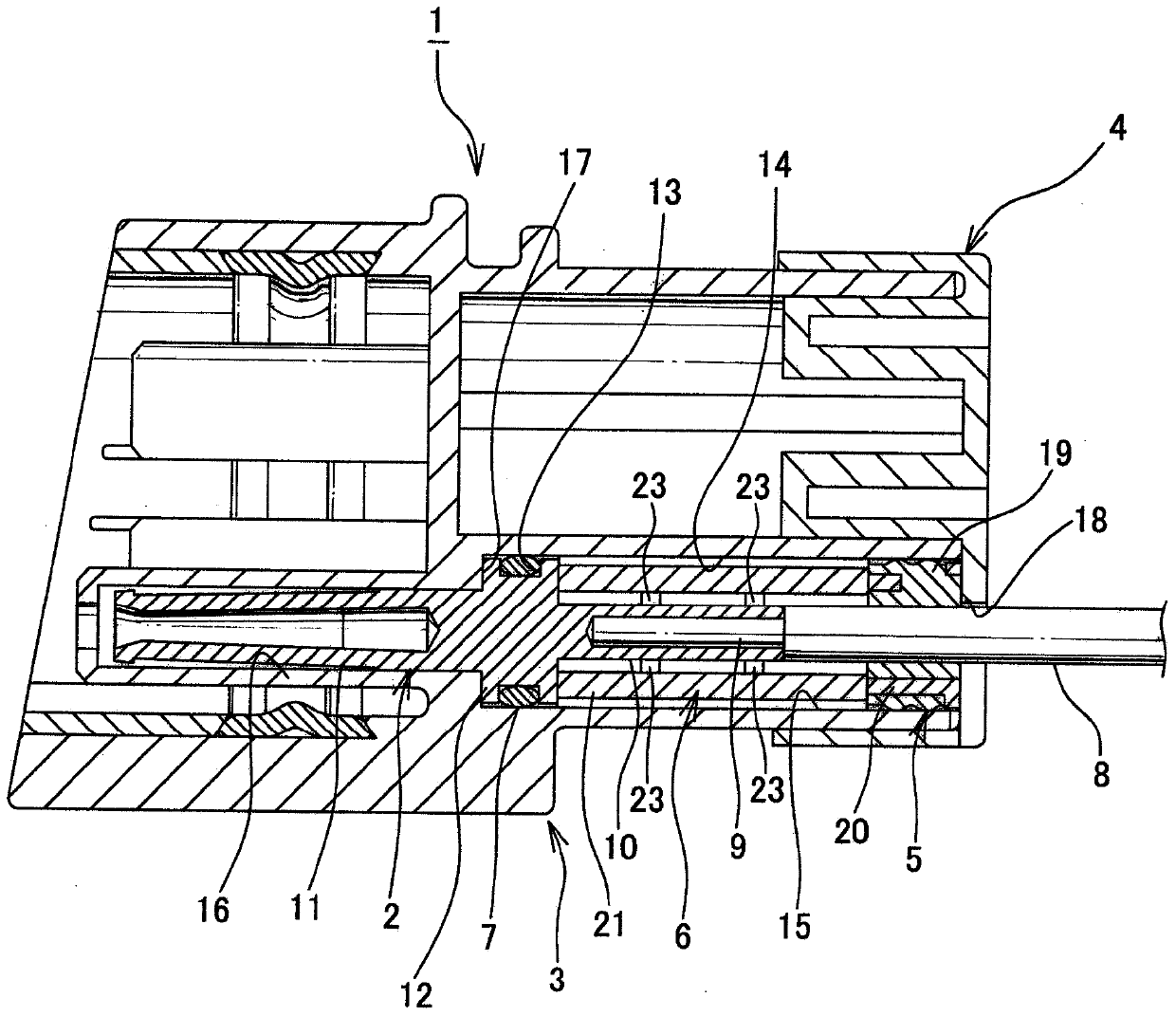
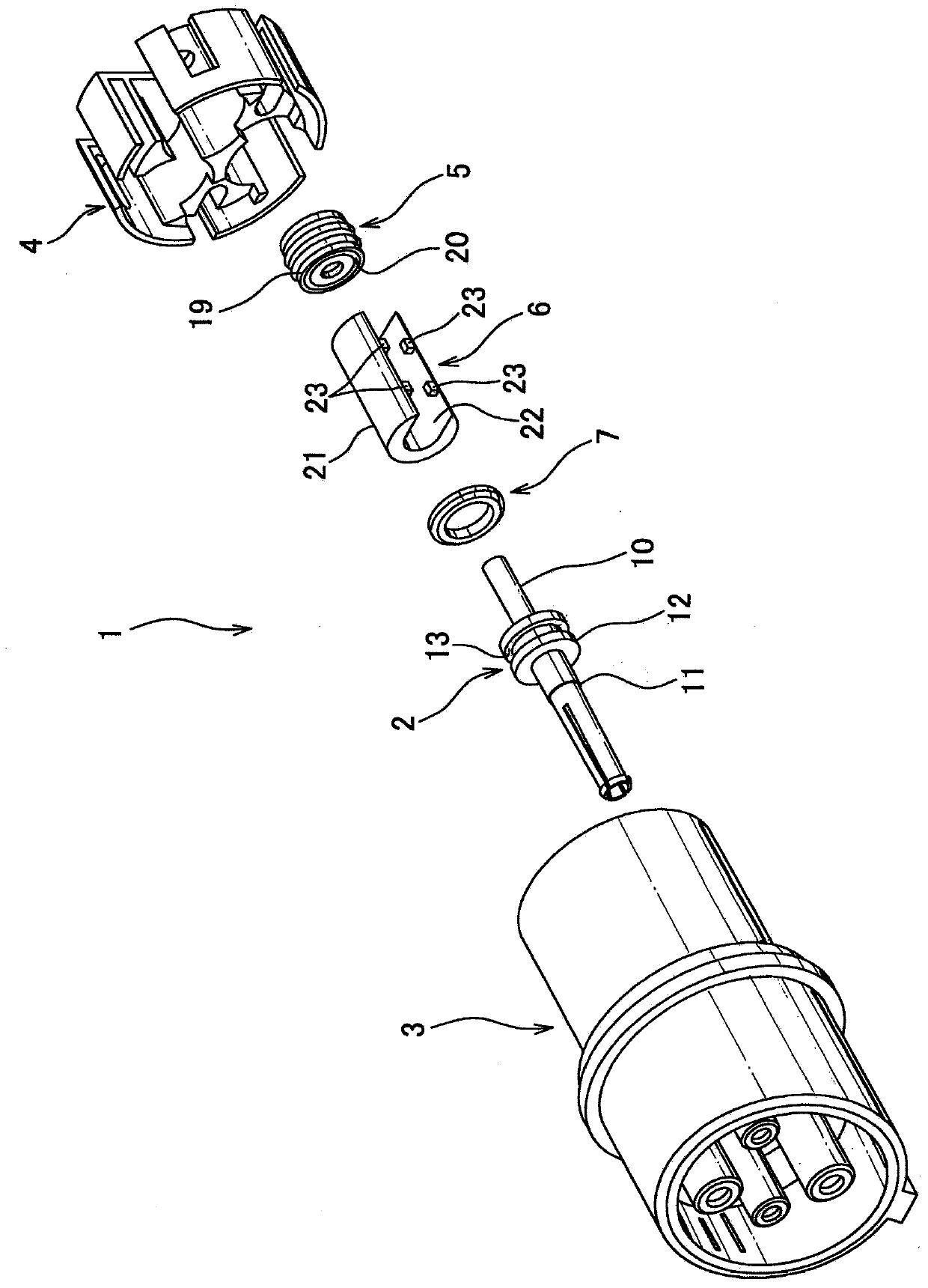
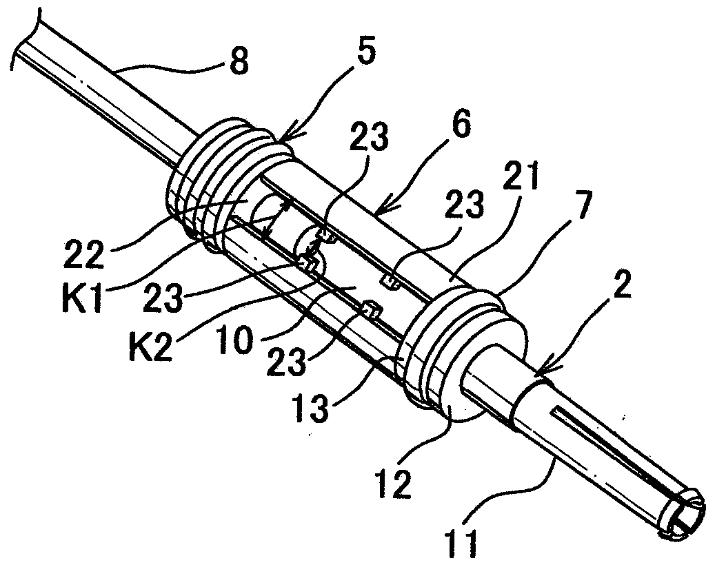
[0050] will refer to Figures 1 to 3 A connector according to one embodiment of the invention is discussed.

[0051] Such as figure 1 , 2 The illustrated connector 1 is provided with: a plurality of terminal fittings 2; a synthetic resin housing 3 provided with a plurality of terminal housings 14 respectively accommodating a plurality of terminal fittings 2; a rear holder 4, the The rear retainer 4 prevents the terminal fittings 2 attached to the end of the housing 3 from falling off from the terminal housing 14; a plurality of rubber packages 5 are press-fitted in each terminal housing 14; A plurality of synthetic resin spacers 6 are housed in the terminal housing 14 , respectively; and a plurality of gaskets 7 are attached to the terminal fittings 2 , respectively. Note that in figure 1 with 2 In , the terminal fittings 2, the rubber packing 5, the gasket 6, and the gasket 7 are shown one by one, while other components are omitted.

[0052] The above-mentioned termin...


PUM


Abstract

A connector is provided with a terminal fitting, a housing, a rear holder, a rubber closures, and a spacers. The spacer is provided with a main body shaped cutaway-circular in cross-section, positioning the electric wire connection part and an electric wire 8 therewithin, and two pairs of projections opposing to each other, projecting from inside of the main body. A width K1 of the cutaway is formed smaller than the diameter of the electric wire. The connector is assembled in such a way that the diametric portion of the electric wire connection part and the electric wire is passed through between the two pairs of projections while the two pairs of projections are enlarged, so as to be positioned within the main body.

Description

technical field [0001] The present invention relates to a connector constituting a wire harness wired in an automobile. Background technique [0002] Various electrical equipment are installed on the car. In order to transmit electric power or control signals to the various electric devices, a wiring harness is arranged in the automobile. The wire harness is composed of a plurality of electric wires and connectors (see Patent Document 1). Figure 4 is a cross-sectional view of a conventional connector. Figure 5 yes Figure 4 An exploded view of the connector shown. Image 6 yes Figure 4 Perspective view of the terminal fitting for the connector shown. [0003] Such as Figures 4 to 6 The above-mentioned connector 301 shown is composed of: a plurality of terminal fittings 302; a synthetic resin housing having a plurality of terminal housings 314 respectively accommodating a plurality of terminal fittings 302; a rear holder 304, which 304 is attached to the end of the h...

Claims


Application Information

Patent Timeline
Patent Type & Authority Applications(China)
IPC IPC(8): H01R13/426H01R13/52H01R107/00
CPCH01R13/426H01R13/521H01R13/5205H01R13/52H01R2107/00H01R2201/26
Inventor 森茂生
Owner YAZAKI CORP
Learn More