
Image encoding method, image decoding method, image encoding device, image decoding device, image encoding program, and image decoding program

A technology of image encoding and image decoding, which is applied in the field of encoding and decoding of distance images, and can solve problems such as the inconsistency between the Z axis and the camera orientation

Inactive Publication Date: 2013-11-20
NIPPON TELEGRAPH & TELEPHONE CORP
View PDF4 Cites 1 Cited by
  • Summary
  • Abstract
  • Description
  • Claims
  • Application Information

AI Technical Summary

Problems solved by technology

In general, the horizontal direction of a captured image is set as the X axis and the vertical direction as the Y axis, so the Z axis coincides with the orientation of the camera. However, there are cases where a common coordinate system is used for multiple cameras, such as Z When the axis does not match the orientation of the camera

Method used


Image

  • Image encoding method, image decoding method, image encoding device, image decoding device, image encoding program, and image decoding program
  • Image encoding method, image decoding method, image encoding device, image decoding device, image encoding program, and image decoding program
  • Image encoding method, image decoding method, image encoding device, image decoding device, image encoding program, and image decoding program

Examples


Embodiment 1

[0095] (Image coding device)

[0096] First, the first embodiment will be described. figure 2 It is a block diagram showing a configuration example of an image coding device according to the first embodiment of the present invention. Such as figure 2 As shown, the image encoding device 100 includes an encoding target frame input unit 101, an encoding target frame storage unit 102, an object number setting unit 103, an object pixel value setting unit 104, an object map generating unit 105, and The subject map storage unit 106, the subject map encoding unit 107, the predicted image generation unit 108, the image signal encoding unit 109, and the multiplexing unit 110.

[0097] The encoding target frame input unit 101 inputs an image frame to be encoded. The encoding target frame storage unit 102 stores the input encoding target frames. The subject number setting unit 103 sets the number of subjects included in a processing area of ​​a predetermined size. The subject pixel value ...

Embodiment 2

[0162] (Image decoding device)

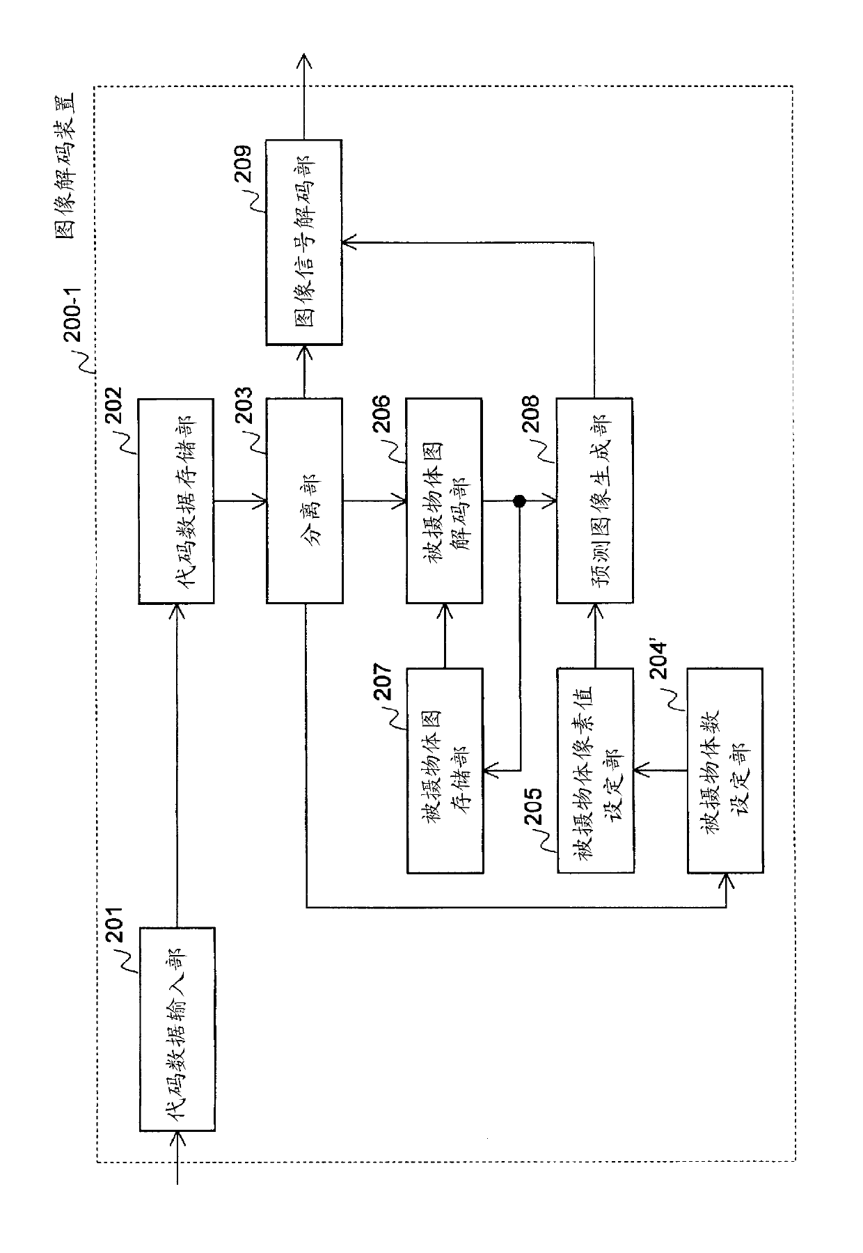
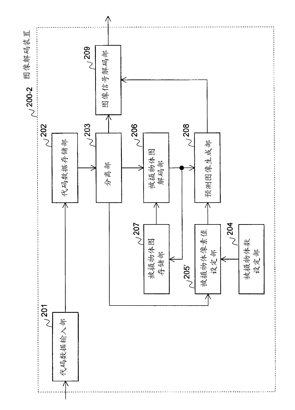
[0163] Next, a second embodiment of the present invention will be described. Figure 15 It is a block diagram showing a configuration example of an image decoding device according to the second embodiment. Such as Figure 15 As shown, the image decoding device 200 includes a code data input section 201, a code data storage section 202, a separation section 203, a subject number setting section 204, a subject pixel value setting section 205, and a subject map decoding section 206 , The subject map storage unit 207, the predicted image generation unit 208, and the image signal decoding unit 209.

[0164] The code data input unit 201 inputs code data of an image frame to be decoded. The code data storage unit 202 stores the input code data. The separation unit 203 separates the multiplexed code data into a plurality of code data that encode different information. The subject number setting unit 204 sets the number of subjects included in a processin...


PUM


Abstract

For each block to be encoded, an image encoding device treats a region having similar image signals in the block as a subject, and sets a single pixel value representing each subject as a subject pixel value so as to be associated with a subject identifier. A subject map generation unit generates a subject map which expresses, with subject identifiers, which subject each pixel in the block belongs to. Using this map, a predicted image generation unit generates a predicted image to be used in prediction of the block to be encoded. A subject map encoding unit encodes the subject map by referring to the subject map used when encoding a reference region that has been encoded.

Description

Technical field [0001] The present invention relates to the encoding and decoding technology of distance image. [0002] This application claims priority based on Japanese Patent Application No. 2011-055238 for which it applied to Japan on March 14, 2011, and the content is quoted here. Background technique [0003] The distance image is an image in which the distance from the camera to the subject is expressed as pixel values. Because the distance from the camera to the subject can also be called the depth of the scene, the distance image is sometimes called the depth image. In addition, because depth is also called depth (Depth), it is sometimes called depth map (Depth Map). In the field of computer graphics, because depth is the information stored in the Z buffer, it is sometimes called Z image or Z image. In addition, in addition to the distance from the camera to the subject, the coordinate value of the Z axis with respect to the three-dimensional coordinate system develope...

Claims


Application Information

Patent Timeline
Patent Type & Authority Applications(China)
IPC IPC(8): H04N7/32H04N19/50H04N19/119H04N19/137H04N19/147H04N19/154H04N19/167H04N19/172H04N19/174H04N19/176H04N19/189H04N19/196H04N19/46H04N19/593H04N19/61H04N19/625H04N19/70H04N19/91H04N19/96
CPCH04N19/00969G06T9/40H04N19/00569G06T9/001H04N19/00545H04N19/00387H04N19/00024H04N19/00769H04N19/20H04N19/46H04N19/597H04N19/96H04N19/50
Inventor 志水信哉木全英明松浦宣彦
Owner NIPPON TELEGRAPH & TELEPHONE CORP
Learn More