Supercharge Your Innovation With Domain-Expert AI Agents!

Drill bit

A drill bit and drill shank technology, which is used in repairing drills, drilling tool accessories, drilling/drilling equipment, etc., can solve problems such as inconvenience in processing and production, and achieve the effects of simple structure, reasonable design and convenient use.

Inactive Publication Date: 2013-11-27
JIANGSU SHENYANG ELEVATOR PARTS
View PDF0 Cites 0 Cited by
  • Summary
  • Abstract
  • Description
  • Claims
  • Application Information

AI Technical Summary

Problems solved by technology

Traditional drill shanks often do not match the various converters that are often used, which brings inconvenience to processing and production

Method used


Image

  • Drill bit
  • Drill bit
  • Drill bit

Examples


Embodiment Construction

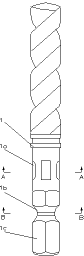
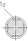
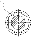
[0010] Such as figure 1 , figure 2 and image 3 As shown, a drill bit of the present invention includes a drill shank 1, and the drill shank 1 includes a section of hexagonal cylinder 1c, see image 3 As shown, the hexagonal cylinder 1c is provided with an annular positioning groove 1b, see figure 2 As shown, the drill shank 1 is also provided with an axial positioning groove 1a. The hexagonal cylindrical drill shank 1 is more suitable for the traditional drill chuck. The hexagonal cylindrical drill shank 1 with a ring-shaped positioning groove 1b is suitable for clamping by a hexagonal converter. , to lock the bit. The drill shank 1 is provided with an axial positioning groove 1a to accommodate different types of converter clamping.

[0011] The above-mentioned examples are only to illustrate the present invention, but not to limit the present invention. The present invention can also be implemented in other ways, which will not be repeated here. Any technical solut...


PUM


Abstract

The invention discloses a drill bit, and belongs to the technical field of machining tools. The drill bit comprises a drill handle (1), wherein the drill handle 1 comprises a hexagonal column body (1c); annular positioning slots (1b) are formed in the hexagonal column body (1c); axial positioning slots (1a) are also formed in the drill handle (1). The drill bit is reasonable in design and simple in structure, is suitable for being clamped by various converters of different types and is convenient to use.

Description

technical field [0001] The invention belongs to the technical field of machining tools, and in particular relates to drill bits. Background technique [0002] In actual mechanical processing production, the use of drill bits accounts for a large proportion. Traditional drill shanks often do not match the various converters that are often used, which brings inconvenience to processing and production. Contents of the invention [0003] In order to solve the above-mentioned shortcomings of the drill bit, the object of the present invention is to provide a drill bit that is suitable for various types of converter clamping. [0004] The purpose of the present invention is achieved by the following technical solutions: a drill bit, including a drill handle, the drill handle includes a section of hexagonal cylinder, the hexagonal cylinder part is provided with an annular positioning groove, and the drill handle is also provided with There are axial positioning grooves. [0005...

Claims


Application Information

Patent Timeline
IPC IPC(8): B23B51/00
Inventor 裴曙光
Owner JIANGSU SHENYANG ELEVATOR PARTS
Features
  • R&D
  • Intellectual Property
  • Life Sciences
  • Materials
  • Tech Scout
  • Unparalleled Data Quality
  • Higher Quality Content
  • 60% Fewer Hallucinations
Learn More