Pneumatic clamp

A technology of pneumatic calipers and air inlets, applied in the direction of brake types, drum brakes, brake actuators, etc., can solve the problems of maintenance and replacement, and achieve simple installation, reduced processing difficulty and cost, and small clamping range. Effect

Active Publication Date: 2017-05-03
KEDE NUMERICAL CONTROL CO LTD
View PDF8 Cites 0 Cited by
  • Summary
  • Abstract
  • Description
  • Claims
  • Application Information

AI Technical Summary

Problems solved by technology

However, when replacing the clamping sleeve, it is still necessary to dismantle the equipment, and maintenance and replacement are very troublesome.

Method used


Image

  • Pneumatic clamp
  • Pneumatic clamp
  • Pneumatic clamp

Examples


Embodiment Construction

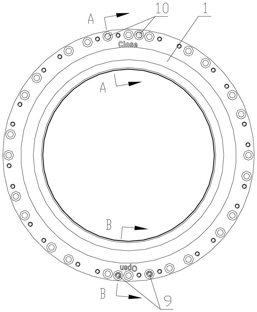
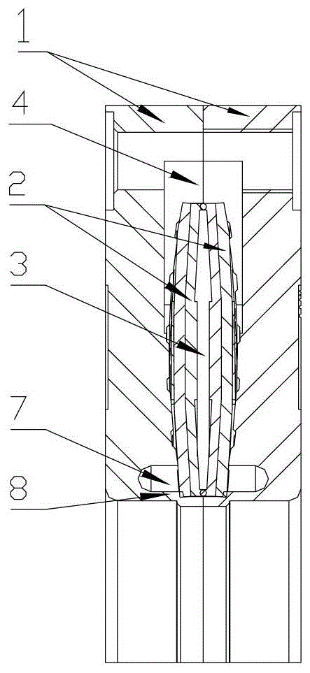
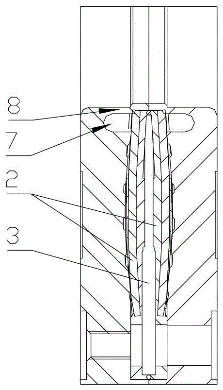
[0039] The specific embodiment of the present invention is shown in the attached drawings. Its structure is composed of two housings 1 of the same size and symmetrical and two spring skin cavities 2 of the same size and symmetrical; A housing 1 is fastened by screws; an inner cavity 3 is formed between the two spring skin cavities 2, and an outer cavity 4 is formed between the housing 1 and the spring skin cavity 2; an outer surface of the housing 1 is processed with a reference surface.

[0040] The shell 1 is made of metal; the spring skin cavity installation groove 5 is machined on its inner side, and the bottom surface of the spring skin cavity installation groove 5 is machined with multiple air grooves 6; 7. Make an extrusion locking piece 8 formed at the inner diameter of the shell 1; a plurality of corresponding countersunk holes and threaded holes for screw installation are machined on the outer diameters of the two shells 1; an inner cavity air intake is machined on the s...


PUM


Abstract

The invention discloses a pneumatic forceps holder, relates to the forceps holder for motor braking, and belongs to the novel pneumatic forceps holder both economic and practical. The pneumatic forceps holder is characterized by comprising two symmetrical shells same in size and two symmetrical spring bellows same in size; the spring bellow are oppositely combined and arranged in the shells and fixed through bolts; an inner cavity is formed between the spring bellows, and an outer cavity is formed between the shells and the spring bellows; one outer side face of the shells serves as a level surface to be processed. The pneumatic forceps holder has the advantages that the pneumatic forceps holder is novel in structure, convenient to process, small in size, convenient to mount and use, less n processing difficulty and precision, long in service life, convenient to maintain and replace and the like.

Description

Technical field [0001] The pneumatic clamp of the present invention relates to a clamp for motor braking. Background technique [0002] At present, the traditional hydraulic clamping method of rotating shaft forms a closed annular oil cavity between the clamping sleeve and the component shell. When high-pressure oil is passed in, the oil forces the clamping sleeve to deform, and the deformation of the clamping sleeve is squeezed The rotary shaft realizes the braking effect through friction. This clamping method has the following shortcomings: [0003] 1. Since the braking force is mainly provided by high-pressure oil, a hydraulic supply system is required in the complete equipment. This will increase the overall size and cost of the device. [0004] 2. Due to the use of high-pressure oil to force the clamping sleeve to deform, it squeezes the rotating shaft to generate friction to achieve the purpose of braking. In order to achieve the desired deformation effect, in addition to c...

Claims


Application Information

Patent Timeline
Patent Type & Authority Patents(China)
IPC IPC(8): F16D49/14F16D65/14F16D121/08F16D125/08F16D125/12F16D125/14
Inventor 冷磊蔡春刚吴福海杜长林毕云李亚鹏
Owner KEDE NUMERICAL CONTROL CO LTD
Why Eureka
Try Eureka