In-place detection device
The technology of a mounting seat and a limit groove is applied in the field of in-position detection devices, which can solve the problems of the influence of the stability of the hydraulic system, the difficulty in meeting the timeliness and accuracy of sending signals, and achieve the effect of improving the speed and accuracy.
- Summary
- Abstract
- Description
- Claims
- Application Information
AI Technical Summary
Problems solved by technology
Method used
Image

Examples
Embodiment Construction
[0014] In order to facilitate the understanding of those skilled in the art, the present invention will be further described in detail below in conjunction with the drawings and specific embodiments.
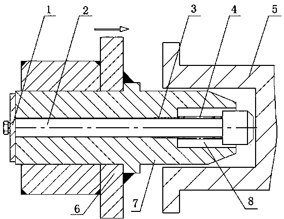
[0015] Reference attached figure 1 , this embodiment is applied to the detection that the sand box 5 is installed in place relative to the turning machine 6. The turning machine 6 can move relative to the sand box 5. The detection device includes a mounting seat 7 and a push rod 2, and the mounting seat 7 is arranged on the turning machine. 6, one end of the ejector rod 2 is provided with an induction plate 1, and the other end of the ejector rod 2 passes through the mounting seat 7 transversely, and can move back and forth along the mounting seat 7, and can be in contact with the sand box 5.
[0016] In this embodiment, a guide sleeve 3 is provided on the ejector rod 2, and the guide sleeve 3 is added during the movement of the ejector rod 2 to ensure the accuracy of the ejecto...
PUM
 Abstract
Description
Claims
Application Information
 - Generate Ideas
- Intellectual Property
- Life Sciences
- Materials
- Tech Scout
- Unparalleled Data Quality
- Higher Quality Content
- 60% Fewer Hallucinations
Browse by: Latest US Patents, China's latest patents, Technical Efficacy Thesaurus, Application Domain, Technology Topic, Popular Technical Reports.
© 2025 PatSnap. All rights reserved.Legal|Privacy policy|Modern Slavery Act Transparency Statement|Sitemap|About US| Contact US: help@patsnap.com