
Optical fiber core butting connector

A butt joint connector and optical fiber core technology, which is applied in the field of optical fiber communication, can solve the problems of large consumption of fiber optic cables and high cost, and achieve the effect of reducing usage and cost

Active Publication Date: 2013-11-27
STATE GRID CORP OF CHINA +1
View PDF4 Cites 9 Cited by
  • Summary
  • Abstract
  • Description
  • Claims
  • Application Information

AI Technical Summary

Problems solved by technology

In order to ensure that any two optical fibers in any of the multiple optical fibers can carry out the transmission of data information exchange, in the prior art, the docking positions corresponding to any two optical fibers in the multiple optical fibers are usually passed through a The fiber optic fiber connection of the root rope leads to the optical fiber core butt connector in the prior art consumes a large amount of rope fiber, and the cost is relatively high

Method used


Image

  • Optical fiber core butting connector
  • Optical fiber core butting connector
  • Optical fiber core butting connector

Examples


Embodiment 1

[0033] The optical fiber core butt connector provided by the embodiment of the present invention includes:

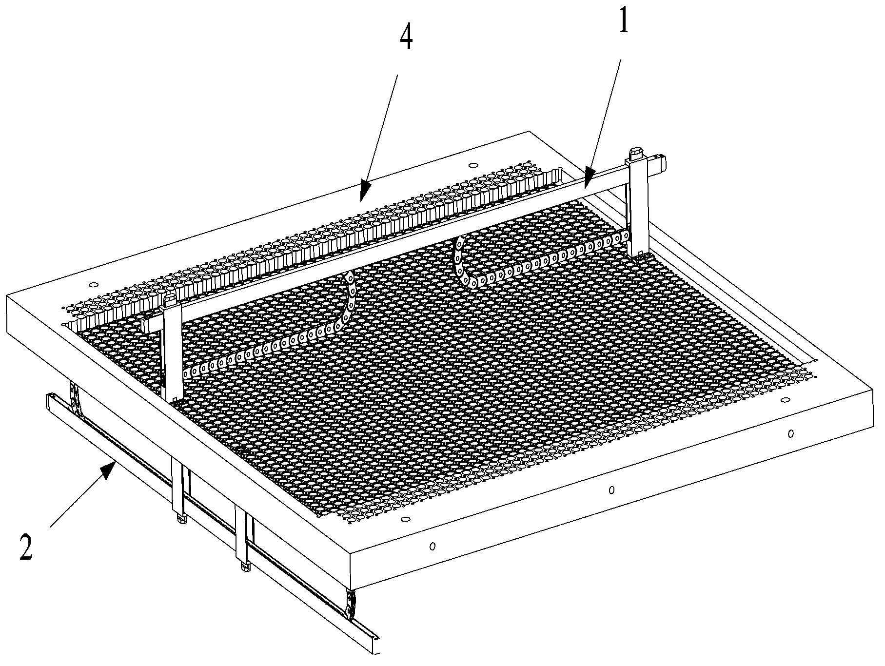
[0034] A number of line connectors 1 parallel to each other, such as figure 1 As shown, the line connector 1 includes: a first sliding rod 11, a first line fiber core connector 12 and a second line fiber core connector 13 that can slide along the first sliding rod 11, wherein the The input end and the output end of the first line fiber core connector 12 are connected by connecting optical fibers, and the input ends and output ends of the second line fiber core connector 13 are connected by connecting optical fibers;

[0035] A number of wire connectors 2 parallel to each other, such as figure 2 As shown, the rope connector 2 includes: a second sliding rod 21, a first rope fiber core connector 22 and a second rope fiber core connector 23 that can slide along the second sliding rod 21, wherein , the first rope fiber core connector 22 is connected to the second rope fib...

Embodiment 2

[0049] The basic structure of the optical fiber core butt connector provided by the embodiment of the present invention is basically similar to the structure in the first embodiment, the difference is that, as Figure 8As shown, the fiber core connector includes: a connecting portion 81; a fixing portion 82, the fixing portion 82 is provided with a cavity 821 through which the left and right sides pass through, and the bottom of the cavity 821 is provided with two through holes side by side 822, the through hole 822 penetrates through the fiber core connector; two optical fiber core link flanges 83, one end of the optical fiber core link flange 83 is fixed in the through hole 822, and the other end There is a second cylindrical portion 833 for fixing the external access fiber core, and at least one fiber core connection flange 83 is provided with a transparent stepped hole 831 inside. Specifically, the fiber core connecting flange 83 is composed of a concentric first cylindric...

Embodiment 3

[0053] On the basis of the second embodiment, in order to facilitate the external device to better clamp the connecting part 81 of the fiber core connector, and drive the fiber core connector to move through the connecting part 81, the embodiment of the present invention core connectors provided, such as Figure 9 As shown, the connecting part 81 is composed of upper and lower parts, wherein, in the direction perpendicular to the direction through which the cavity 821 penetrates, the cross-sectional area of ​​the upper part of the connecting part 81 is larger than that of the lower part of the connecting part 81. Cross-sectional area, so that the upper part of the connecting part 81, the lower part of the connecting part 81 and the fixing part 82 form a groove shape, so that external devices can be easily formed by using the lower part of the connecting part 81 The groove clamps the fiber core connector to move up and down.

[0054] To sum up, the optical fiber core butt conn...


PUM


Abstract

The embodiment of the invention discloses an optical fiber core butting connector. The optical fiber core butting connector comprises a plurality of circuit connectors which are mutually parallel and a plurality of cord circuit connectors which are mutually parallel. Each circuit connector comprises a first sliding rod, a first circuit fiber core connector and a second circuit fiber core connector, wherein the first circuit fiber core connector and the second circuit fiber core connector can slide along the first sliding rod, the input end of the first circuit fiber core connector and the output end of the first circuit fiber core connector are connected through a connecting optical fiber, and the input end of the second circuit fiber core connector and the output end of the second circuit fiber core connector are connected through a connecting optical fiber. Each cord circuit connector comprises a second sliding rod, a first cord circuit fiber core connector and a second cord circuit fiber core connector, wherein the first cord circuit fiber core connector and the second cord circuit fiber core connector can slide along the second sliding rod and are connected through a connecting optical fiber. The optical fiber core butting connector has the advantages that automatic joint of a plurality of optical fibers in an optical network can be achieved, switch transmission of data information is achieved, the usage amount of cord circuit optical fibers is reduced, and cost is reduced.

Description

technical field [0001] The invention relates to the technical field of optical fiber communication, in particular to an optical fiber core butt connector. Background technique [0002] With the rapid development of power grid construction and the continuous improvement of the automation of power system equipment, the optical fiber power communication network has also achieved unprecedented development. [0003] At present, as the basic bearer network of optical fiber communication transmission - the optical fiber network, its operation and maintenance work is still in the original manual mode, that is, it usually needs to manually go to the site to perform fiber jumping operations to realize the docking exchange between different optical fibers. However, due to the geographical dispersion, cumbersome manual switching operations and many other factors, such manual operations in daily life are huge and time-consuming. Therefore, how to realize the automatic docking and exchang...

Claims


Application Information

Patent Timeline
Patent Type & Authority Applications(China)
IPC IPC(8): G02B6/38G02B6/28
Inventor 俞红生朱承治范雪峰李建刚吕舟黄红兵
Owner STATE GRID CORP OF CHINA
Learn More