A mop chassis and a dehydration bucket fixing seat used in conjunction with it

A fixed seat and chassis technology, which is applied in the field of mop buckets, can solve the problems of one-way bearings and base springs that are fragile, reduce service life, and short service life, so as to reduce the time for cleaning the drive shaft, prolong the service life, and operate humanely effect

Active Publication Date: 2016-08-03
GUANGZHOU GOOD WIFE ARTICLES
View PDF6 Cites 0 Cited by
  • Summary
  • Abstract
  • Description
  • Claims
  • Application Information

AI Technical Summary

Problems solved by technology

[0004] One-way bearings and base springs are easily damaged and have a short service life;
[0005] The stolen goods on the mop head, such as hair and thread ends, are easy to get entangled on the drive shaft in the dehydration net, which will affect the use and reduce the service life;

Method used


Image

  • A mop chassis and a dehydration bucket fixing seat used in conjunction with it
  • A mop chassis and a dehydration bucket fixing seat used in conjunction with it
  • A mop chassis and a dehydration bucket fixing seat used in conjunction with it

Examples


Embodiment 1

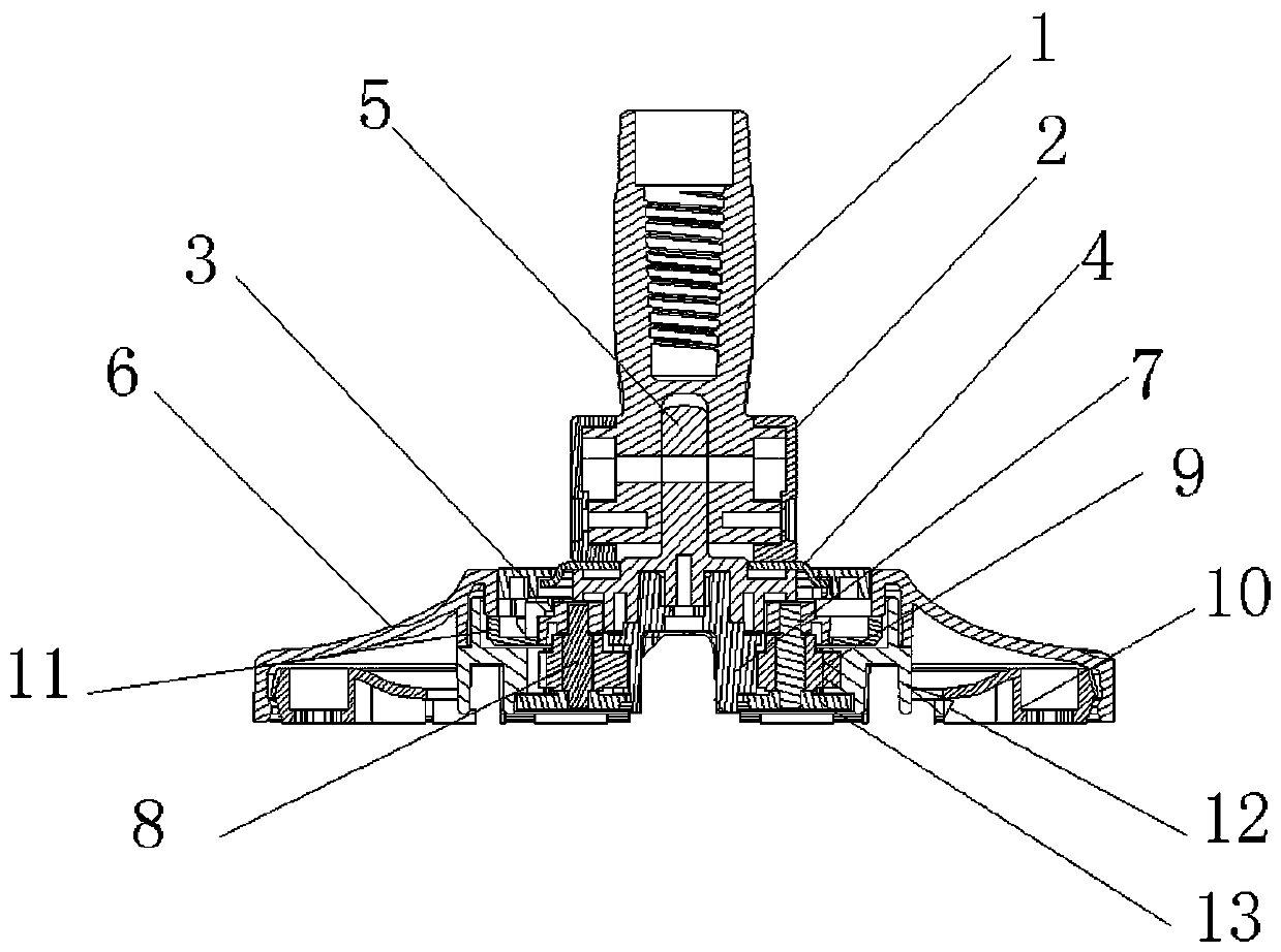
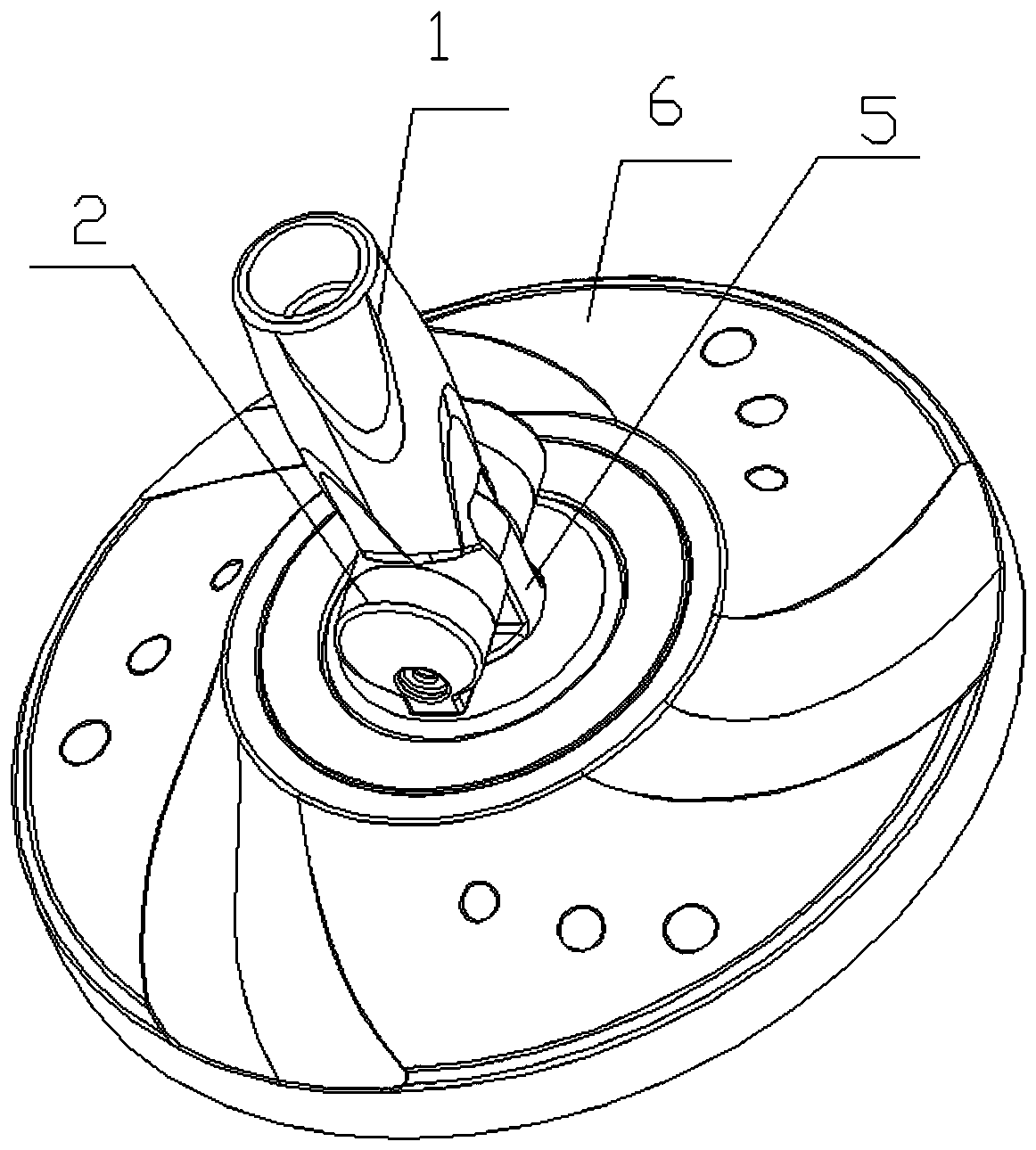
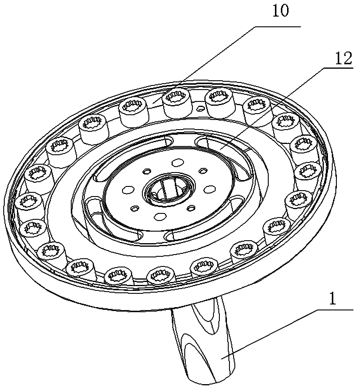
[0026] Such as Figure 1~4 As shown, the mop chassis provided in this embodiment includes: a turntable frame 1, a rotating positioning core 5, a cotton yarn turntable cover 6, a cotton yarn turntable bottom 10, and a speed reduction mechanism. The turntable frame 1 is connected with the rotating positioning core 5, and the rotating positioning core 5 is connected to the cotton yarn turntable cover 6, and the bottom of the cotton yarn turntable is clamped on the inner cover of the cotton yarn turntable cover. The bottom of the cotton yarn turntable is used to fix the cotton yarn. The mechanism is connected with the rotary positioning core 5 . In this embodiment, the deceleration mechanism is specifically: comprising a deceleration gear 7, a deceleration pinion 9, and a deceleration internal gear 12, the deceleration gear 7 is connected with the rotating positioning core 5, the deceleration gear 7 and the deceleration pinion 9 mesh, and the deceleration pinion 9 meshes with the...

Embodiment 2

[0032] Such as Figure 5 As shown, the present embodiment provides a dehydration bucket fixing base that matches the above-mentioned mop chassis. The fixing base includes a base 18, a dehydration net drive shaft 15 and a fixing device for fixing the deceleration internal gear. A groove is arranged in the middle of the base, and the groove The dehydration net transmission shaft 15 is arranged inside, and a positioning joint 14 is assembled above the dehydration net transmission shaft 15. It is an interference fit between the dehydration net transmission shaft 15 and the positioning joint 14, and the positioning joint 14 cooperates with the speed reduction mechanism in the mop chassis; The fixing device for fixing the decelerating internal gear in the embodiment is the boss 19 arranged above the base, and the protruding post 19 can be inserted into the groove of the decelerating internal gear to fix the decelerating internal gear, so as to decelerate the rotation of the internal ...


PUM


Abstract

The invention discloses a mop base plate and a dewatering barrel fixing seat assorted with the mop base plate. The mop base plate comprises a rotary table rack, a rotary positioning core, a cotton yarn rotary table cover, a cotton yarn rotary table bottom and a reducing mechanism. The rotary table rack is connected with the rotary positioning core which is connected to the cotton yarn rotary table cover, the cotton yarn rotary table cover is connected with the cotton yarn rotary table bottom in a clamped manner, and the reducing mechanism is arranged between the cotton yarn rotary table cover and the cotton yarn rotary table bottom, and is connected with the rotary positioning core. According to the arrangement of the mop base plate, sundries such as cotton yarns or hairs can be prevented from twining a transmission shaft and jamming the same, so that operating efficiency can be improved and service life can be prolonged. In addition, operation is simple since the mop base plate can be rotated by direct manual operation during use, traditional way of operating the mop base plate can be changed by having the feet liberated, and accordingly the operation is more humanized.

Description

technical field [0001] The invention belongs to the field of cleaning appliances, and in particular relates to a mop bucket. Background technique [0002] The mop is an indispensable cleaning product in life. The existing mop is mainly a mop that can replace the mop head and a mop that can be wrung out: the mop that replaces the mop head still needs human hands to wash the mop head, which is inconvenient and inconvenient. Hygienic; the mop that can wring water is divided into extrusion type and rotary type. Due to the limited force of the extrusion type mop, the mop head is not very clean and often cannot be wrung out, while the rotary type mop uses The principle of centrifugal force uses a little manpower to make the mop head dry in the washing machine, so it is loved by people. [0003] The rotary mops in the prior art all have the rotating part arranged in the mop bucket. When cleaning or wringing out, the mop head is put into the dehydration net, and the dehydration net...

Claims


Application Information

Patent Timeline
Patent Type & Authority Patents(China)
IPC IPC(8): A47L13/58
Inventor 尹建兰
Owner GUANGZHOU GOOD WIFE ARTICLES
Why Eureka
Try Eureka