
Transportation system and method of high concentration solid granule suspending solution

A solid particle, conveying system technology, applied in pipeline systems, gas/liquid distribution and storage, mechanical equipment, etc., can solve problems such as failure to work properly, pipeline blockage, and system impact

Inactive Publication Date: 2012-03-28
罗文峰
View PDF8 Cites 14 Cited by
  • Summary
  • Abstract
  • Description
  • Claims
  • Application Information

AI Technical Summary

Problems solved by technology

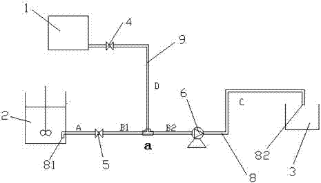
[0004] In view of the above defects, the purpose of the present invention is to provide a high-concentration solid particle suspension delivery system and method to solve the problem of pipeline blockage, valves and delivery problems caused by the deposition of solid particles in the suspension in the pipeline in the prior art. The phenomenon that the pump is stuck, which affects the problem that the whole system cannot work normally

Method used


Image

  • Transportation system and method of high concentration solid granule suspending solution
  • Transportation system and method of high concentration solid granule suspending solution
  • Transportation system and method of high concentration solid granule suspending solution

Examples


Embodiment 1

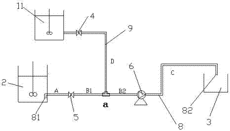
[0038] Please refer to figure 2 , the discharge nozzle 82 is higher than the liquid level of the solid particle suspension in the mixing device 2, and the discharge nozzle 82 is always lower than the liquid level of the clear water tank 11, and its function is to flush the delivery pipeline 8 with clean water In this process, the clean water can flow through the delivery pipeline B from the clean water tank 11 relying on potential energy 2 Section, delivery pump 6 and section C of delivery pipeline; when flushing section A of delivery pipeline, delivery valve 5 and delivery pipeline B 1During the section, because the discharge nozzle 82 of the delivery pipeline 8 should be higher than the liquid level of the suspension in the mixing device 2, the clear water will only flow to the A section of the delivery pipeline, but not to the C section of the delivery pipeline. .

Embodiment 2

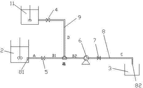
[0040] Please refer to image 3 , the liquid level of the clear water tank 11 is higher than the liquid level of the suspension in the mixing device 2, and the discharge nozzle position of the section C of the conveying pipeline is lower than the liquid level of the suspension in the mixing device 2. The trend of clear water is controlled by adding a control valve 7, that is, a control valve 7 is connected in series behind the delivery pump 6. In the process of flushing the delivery pipeline 8 with clean water, open the flushing valve 4 and the control valve 7, close the delivery valve 5, and the clean water can flow through the delivery pipeline B from the clean water tank 11 relying on potential energy 2 Section, delivery pump 6 and section C of delivery pipeline; when flushing section A of delivery pipeline, delivery valve 5 and delivery pipeline B 1 During a period of time, open the delivery valve 5 and close the control valve 7, and the clean water can flow through the d...


PUM


Abstract

The invention discloses a transportation system and method of high concentration solid granule suspending solution, wherein the system includes a mixing device for forming the high concentration solid granule suspending solution; a transporting pump and a suspending solution reaching device needing the high concentration solid granule suspending solution, wherein the mixing device, the transporting pump and the suspending solution reaching device are in turn connected via a transporting pipe. The system also includes a clean water device for rinsing the transporting pipe and the transporting pump, which is connected with the transporting pipe via a rinsing pipe; the rinsing pipe of the clean water device is provided with a rinsing valve and the transporting pipe is arranged with a transporting valve. In the mixing device, the feeding pipe port of the transporting pipe is downward bent, and the feeding pipe port of the transporting pipe and the bottom part of the mixing device are formed with a gap. The invention solves the problem in the prior art that the whole system cannot work normally because the solid granules in the suspending solution are deposited in the pipe to block the pipe and clamp the valve and the transporting pump.

Description

technical field [0001] The invention relates to a high-concentration solid particle suspension delivery system and method. Background technique [0002] The solid particle suspension is composed of solid particles and a dispersed phase (such as water). The suspension is prepared in the mixing device, and it is best to keep stirring to keep the suspension state stable. [0003] At present, the delivery system of high-concentration solid particle suspension consists of a mixing device and a suspension arrival device. The mixing device is a device for preparing a solid particle suspension, and the suspension arrival device is a device that requires a suspension. The arrival device is connected by a pipeline, and a delivery pump is set in the pipeline between the mixing device and the suspension arrival device, and a valve is set in the delivery pipeline of the mixing device, the valve is opened, the delivery pump is started, and the mixing The suspension in the feeding device ...

Claims


Application Information

Patent Timeline
IPC IPC(8): F17D1/14F17D3/01F17D3/16
Inventor 罗文峰
Owner 罗文峰
Learn More