Flow construction method of underground pipe gallery inner mold system

An underground pipe gallery and construction method technology, which is applied in water conservancy projects, artificial islands, underwater structures, etc., can solve the problems of difficult production and transportation, long waiting time for demoulding, and large consumption of materials, and saves energy. Moving and preparation time, reduced demolding waiting time, ease of fabrication and shipping

Inactive Publication Date: 2017-05-31
CHINA FIRST METALLURGICAL GROUP
View PDF5 Cites 10 Cited by
  • Summary
  • Abstract
  • Description
  • Claims
  • Application Information

AI Technical Summary

Problems solved by technology

Generally, the internal formwork system of underground pipe gallery adopts the combination of traditional formwork and scaffolding, which requires a large amount of work and material consumption for erection, dismantling, and transportation. Therefore, it takes a long time, has low efficiency and high cost. The current advanced internal formwork system for underground pipe gallery The mold base automatic control unit is adopted. The mold base automatic control unit includes a trolley and an electrical control system. A retractable top formwork and side formwork are installed on the trolley. The formwork, side formwork and tucked corner formwork are extended to the design position for support. After the pouring is completed, the top formwork, side formwork and tucked corner formwork are retracted, and the trolley moves to the next section, so that the overall move...

Method used


Image

  • Flow construction method of underground pipe gallery inner mold system
  • Flow construction method of underground pipe gallery inner mold system

Examples


Embodiment Construction

[0027] The present invention will be described in detail below in conjunction with the accompanying drawings and embodiments.

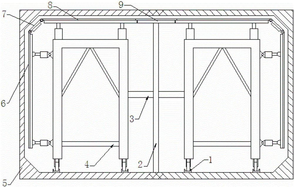
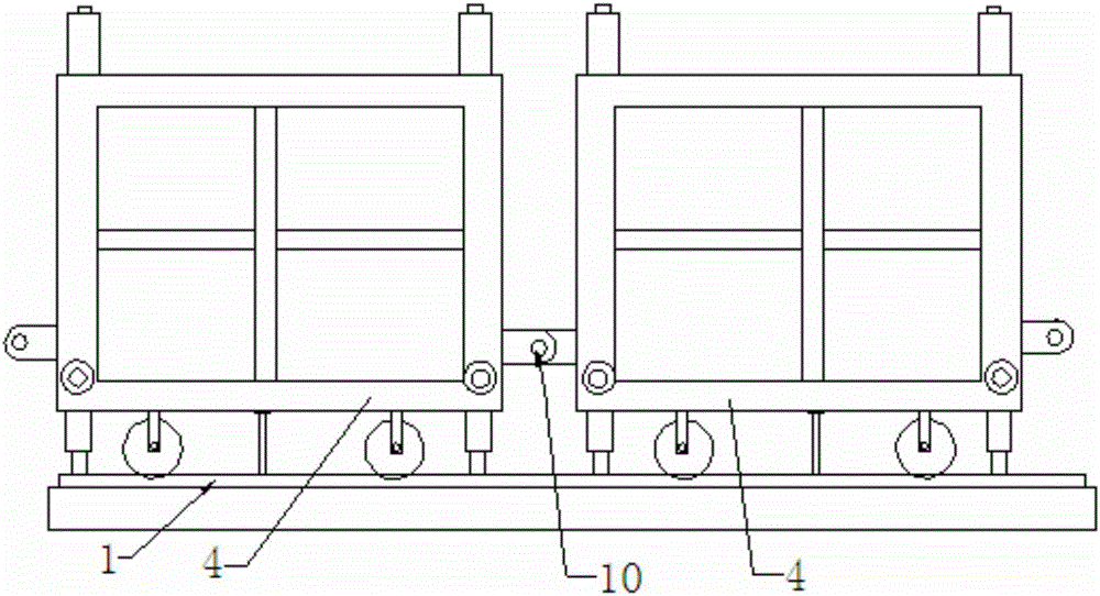
[0028] A flow-through construction method for the internal formwork system of an underground pipe gallery, such as figure 1 As shown, a pair of formwork automatic control units are set on the same section of the pipe gallery. The formwork automatic control unit includes a trolley 4 and an electrical control system. A retractable top formwork 8 and a side formwork 6 are installed on the trolley 4. A tucked angle formwork 7 is provided between the top formwork 8 and the side formwork 6, and there is a distance between the two top formworks 8. During construction, the top formwork 8, the side formwork 6 and the tucked angle formwork 7 are stretched to the design position and then placed on the two top formworks. Install independent early demolition formwork 9 at the distance between formwork 8, top formwork 8, side formwork 6, tuck angle formwork 7 and e...


PUM


Abstract

The invention relates to a flow construction method of an underground pipe gallery inner mold system. A pair of mold frame automatic control units is arranged on the same section of a pipe gallery. During construction, after top mold plates, side mold plates and corner mold plates stretch to design positions, an independent early demounting mold plate is mounted at the clearance position of the two top mold plates; complete supporting is formed by the top mold plates, the side mold plates, the corner mold plates and the early demounting mold plate, and pouring is carried out; after concrete reaches certain strength, the top mold plates, the side mold plates and the corner mold plates retract and move to the next work station along with trolleys; and meanwhile, the early demounting mold plate is kept in a supporting state, the early demounting mold plate is demounted after the concrete reaches certain strength, and the demounted early demounting mold plate and the mold frame automatic control units reaching the next work station cooperate to complete subsequent supporting. According to the method, the mold demounting wait time is shortened, the movement and preparation time of the mold frame automatic control units is saved, and repeated utilization is convenient.

Description

technical field [0001] The invention belongs to the technical field of construction of an underground pipe gallery, and in particular relates to a flow-through construction method of an internal mold system of an underground pipe gallery. Background technique [0002] The construction of urban underground comprehensive pipe gallery is an important measure to innovate urban infrastructure construction. The underground pipe gallery has the characteristics of relatively regular size, large cross-sectional span, and long pipe gallery length. Therefore, the underground pipe gallery internal mold system can be used for pouring support. Generally, the internal formwork system of underground pipe gallery adopts the combination of traditional formwork and scaffolding, which requires a large amount of work and material consumption for erection, dismantling, and transportation. Therefore, it takes a long time, has low efficiency and high cost. The current advanced internal formwork syst...

Claims


Application Information

Patent Timeline
IPC IPC(8): E02D29/045
CPCE02D29/10E02D2250/0007
Inventor 张芝峰徐军马秉俊杨佳华郭继舟
Owner CHINA FIRST METALLURGICAL GROUP
Why Eureka
Try Eureka