Turbine rotor arrangement system
A turbine and rotor technology, applied in the directions of preventing leakage, supporting elements of blades, engine elements, etc., can solve the problems of low safety performance and economic performance, large overall span of the rotor, low safety performance, etc., and is conducive to the overall structural design. , the effect of shortening the overall span, improving safety and economic performance
Pending Publication Date: 2021-11-16
SHANGHAI POWER EQUIP RES INST
0 Cites 2 Cited by
AI-Extracted Technical Summary
Problems solved by technology
[0002] Supercritical carbon dioxide turbine rotors are suitable for power generation equipment. Most of the current balance pistons are placed in the high-temperature section of the turbine. Due to the large air leakage radius, in order to control the air leakage, the length of the balance piston is relatively long, resulting in The high temperature section is too long, which makes the safety ...
Method used
In this embodiment, the second low temperature zone 30 is also provided with a second dry gas seal 303, the second dry gas seal 303 is sleeved on the rotating shaft 1, and the second dry gas seal 303 and the third seal 302 are respectively located at the second On both sides of the three air inlets 301, the second dry gas seal 303 is away from the second exhaust port 206 relative to the third seal 302, and is used to seal the inner cylinder. In this embodiment, the inner diameter of the first dry gas seal 102 is larger than the inner diameter of the second dry gas seal 303 . By setting the rotating shaft 1 in the inner cylinder and controlling the temperature and pressure of the cooling air, it can be ensured that the temperature and pressure of the cooling air entering from the first air inlet 103 and the third air inlet 301 are maintained between the first dry gas seal 102 and the The allowable temperature and allowable pressure range of the second dry gas seal 303, so as to ensure that the first dry gas seal 102 and the second dry gas seal 303 respectively sleeved on the boss 101 and the rotating shaft 1 can be effectively sealed, thereby realizing Effective sealing of the rear and the inner cylinder, while realizing the axial force balance of the rotating shaft 1. This solves the technical problems existing in the prior art: when dry gas seals are arranged on both sides of the turbine, such as using a conventional leak-by system, the minimum environmental pressure of the dry gas seal is the exhaust pressure of the turbine, and the supercritical state The dry gas seal system under the air is prone to failure due to frictional heat.
The intake and exhaust of the cooling air of the turbine rotor arrangement system provided by the present embodiment are independent, and the gas source is stable, and the pressure of the cooling air intake can be adjusted as required, so that the balance thrust can be realized without arranging the balance disc . And through the improvement of the turbine rotor arrangement system, it is beneficial to greatly shorten the overall span of the rotor, which is beneficial to the ove...
Abstract
The invention relates to the technical field of turbine rotating machinery, and discloses a turbine rotor arrangement system. The turbine rotor arrangement system comprises a turbine cylinder, a rotating shaft, a boss and a first air inlet, the rotating shaft is arranged in the turbine cylinder, and the rotating shaft is sequentially provided with a first low-temperature area, a high-temperature area and a second low-temperature area in the axial direction of the rotating shaft; the boss is arranged in the first low-temperature area of the rotating shaft, and the periphery of the boss is sleeved with a first dry gas seal; and the first air inlet is formed in the side, close to the high-temperature area, of the boss and used for communicating with a cooling air source. According to the turbine rotor arrangement system, a balance disc does not need to be arranged, through-flow and axial thrust generated by the sealing teeth are balanced through thrust generated by the differential pressure before and after the boss of the dry gas seal is installed, the overall operation efficiency of a unit is high, the overall span of the rotor is small, and the safety performance and the economic performance of the unit are good.
Application Domain
Blade accessoriesLeakage prevention +1
Technology Topic
PhysicsRotary machine +4
Image
Examples
- Experimental program(1)
Example Embodiment
[0031] The present invention is further detailed below with reference to the accompanying drawings and examples. It will be appreciated that the specific embodiments described herein are merely illustrative of the invention and are not limited thereto. It will also be also to be described, and only the parts associated with the present invention are shown in the drawings rather than all structures.
[0032] In the description of the present invention, the term "connected", "connection", "fixed", unless otherwise specified, "connected", "fixed", for example, may be a fixed connection, or a detachable connection, or integral However, it can be a mechanical connection or an electrical connection; it can be directly connected, or the intermediate medium can be indirectly connected, which may be a communication between two elements or two components. Relationship. The specific meaning of the above terms in the present invention will be appreciated to those skilled in the art.
[0033] In the present invention, unless otherwise expressly specified and defined, the first feature "upper" or "lower" or "lower" may include direct contact between the first and second features, and may include first and second features. It is not directly in contact with additional feature between them. Moreover, the first feature "above", "above" and "upper" include the first feature to the second feature is directly above and obliquely, or only means that the first feature level is higher than the second feature. The first feature is in the second feature "under", "below" and "below" include the first feature to the second feature is below and obliquely, or only the first feature level height is less than the second feature.
[0034] In the description of the present embodiment, the terms "upper", "lower", "left", "right" oriented orientation are based on the orientation or positional relationship shown in the drawings, only for easy description and simplification operation. Instead of indicating or implying that the device or component must have a specific orientation, constructing and operating in a particular direction, and thus is not to be construed as limiting the invention. Furthermore, the term "first", "second" is only used to distinguish in the description and there is no special meaning.
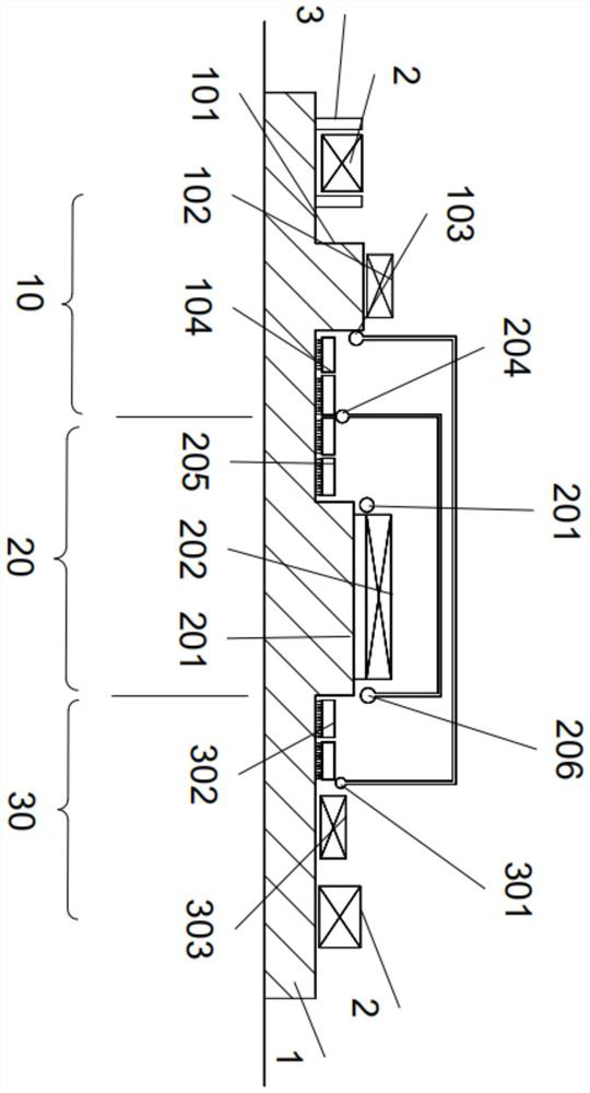
[0035] like figure 1 As shown, the present embodiment provides a turbine rotor arrangement system including a turbine, rotating shaft 1, a boss 101, and a first intake port 103, and the rotating shaft 1 is disposed in a pan-cylinder, rotating shaft 1 The first low temperature region 10, the high temperature zone 20, and the second low temperature zone 30 are disposed along the axial direction of the axis 1, and the boss 101 is disposed in the first low temperature region 10 of the rotating shaft 1, and the outer circumferential casing of the boss 101 is provided A dry gas seal 102, the first intake port 103 is disposed on one side of the boss 101 close to the high temperature zone 20, and the first intake port 103 is used to connect the cooling gas source. The intake pressure of the cooling gas is p 0 Temperature T 0 , P 0 T 0 The air intake parameters of turbine gases. Among them, the cooling gas source extracts the cooling gas from the circulatory system, and the temperature of the cooling gas is less than the temperature capable of the first dry gas seal 102. Adjusting cooling gas into the intake pressure P in the first intake port 103 by adjusting the valve 0 , Adjust the cooling gas into the intake temperature T of the first intake port 103 by electric heater. 0 Therefore, the pressure P by the cooling gas entered by the first intake port 103 by the intake pressure and intake temperature of the cooling gas source can be realized. 0 And temperature T 0. The air conditioning of the first intake port 103 is used to cool the rotor, and the temperature of the rotor can be reduced by adjusting the temperature of the cooling gas; in the above structure, the first dry gas seal 102 is the first air intake 103. The air pressure, the other side is atmospheric pressure, and the axial thrust of the rotor is balance the axial thrust by the differential pressure on both sides of the first dry gas seal 102, that is, the adjustment P can be achieved without setting a balancing disk. 0 Size to adjust the size of the balance. Further, the turning rotor arrangement system provided in this embodiment solves the problem in the prior art: when the balance piston is arranged in the high temperature segment of the turbine, due to the large air leakage radius, the amount of air leaks must be extended to extend the length of the balance piston, This will result in too long, high temperature segments, too long, easy to affect the safety performance of the unit.
[0036]Specifically, both ends of the rotating shaft 1 respectively provided a bearing 2, and the bearing 2 is used to support the shaft 1, and there is a bearing thrust disk 3 on both sides of the shaft 1 of the first low temperature zone 10. More specifically, the inner diameter of the first dry gas seal 102 is larger than the outer diameter of the bearing thrust disk 3. Since the bearing thrust disc 3 is integral with the rotor, the inner diameter of the first dry gas seal 102 is larger than the outer diameter of the bearing thrust disk 3 such that the first dry gas seal 102 can be smoothly set from one end of the rotary shaft 1 The outer circumference of the boss 101, that is, the first dry gas seal 102 facilitates the mounting and disassembly, can effectively avoid the limitations of the shaft sealing gas system, the cooling gas system, the dry gas seal, and the carbon ring seal arrangement.
[0037] Further, the turbine rotor arrangement system further includes a turbine rotor 201, a second intake port 203, a first venture port 204, and a second exhaust port 206, and the turbine rotor 201 is disposed on the high temperature zone 20 of the rotary shaft 1. The outer circumference of the turbine rotor 201 is provided with a blade 202, and the second intake port 203 is provided on the high temperature zone 20 of the rotating shaft 1 for connecting the high temperature source to drive the blade 202 to rotate the shaft 1 rotation, first The exhaust port 204 is disposed between the high temperature zone 20 of the shaft 1 and is located between the first intake port 103 and the second intake port 203. The second exhaust port 206 is disposed in the high temperature zone 20 of the rotating shaft 1, and the second exhaust port 206 communicates with the first exhaust port 204, the second intake port 203 and the second exhaust port 206 are respectively disposed on the turbine rotor 201, respectively. On both sides, the second exhaust port 206 is remote from the boss 101 with respect to the second intake port 203, and the second exhaust port 206 is used to collect the high temperature gas passing through the blade 202. The pressure of high temperature gas at the second intake port 203 is P 1 Temperature T 1 , P 1 T 1 Take turning air intake parameters, the exhaust pressure of the first vent air port 204 and the second exhaust port 206 is P 2 Temperature T 2 , P 2 T 2 Turnover exhaust parameters, P 1 , T 1 , P 2 T 2 The value is determined by the system, the pressure of the cooling gas extracted from the circulatory system is greater than the exhaust pressure P 2. The cooling gas supplied from the first intake port 103 is discharged from the first venting port 204 after cooling the shaft 1, and the high temperature gas enters the blade 202 from the second intake port 203 to rotate from the second row. The gas port 206 is discharged, and a little high temperature gas leakage from the second intake port 203 is discharged from the first vent air port 204, and by connecting the second exhaust port 206 in the first exhaust port 204, flow can be flowed to the first The high temperature gas of a row of air port 204 and the blade 202 are discharged together with the rotary shaft 1 to complete the high temperature gas of the operation, and ensure that the rotating shaft 1 works in an orderly manner.
[0038] In the present embodiment, the toner is provided in the outer cylinder and the inner cylinder, and the inner cylinder is disposed in the outer cylinder, and the rotating shaft 1 is disposed in the inner cylinder, and the first vent air port 204 and the second exhaust port 206 are passed through the inner cylinder and the outer cylinder. The gap is connected. Of course, in other embodiments, the microcomputer may be a single layer cylinder, and the first exhaust port 204 and the second exhaust port 206 can communicate through the communication tube or in the cylinder, in this embodiment. Under the above structure, the high temperature gas pair shaft 1 generates an axial force to be offset from the cooling gas pressure at the first intake port 103 to minimize, thereby minimizing the axial force of the rotating shaft 1 and does not need to arrange the balancing plate.
[0039] Preferably, the first intake port 103 and the first venting port 204 are provided with a first seal 104, and the first seal 104 is sleeved in the rotating shaft 1, and the first exhaust port 204 and the first intake port 103 can pass through The gap between the first seal 104 and the rotating shaft 1 is in communication. The cooling gas from the first intake port 103 into the process of discharged from the first vent 204, the cooling gas is cooled to the first seal 104, and the clearance from the first seal 104 and the gap between the rotary shafts The gas can be further cooled to the first seal 104 to ensure the effective seal of the first seal 104, thereby achieving the reduction in the air volume, shortens the span of the shaft 1, and improve the security of the unit; The cooling gas into which it can also prevent the high temperature gas from the second intake port 203 to flow to the first seal 104.
[0040] Preferably, a second seal 205 is provided between the second intake port 203 and the first exhaust port 204, and the second seal 205 is sleeved in the rotating shaft 1, and the second intake port 203 and the first exhaust port 204 can pass. The gap between the second seal 205 and the rotating shaft 1 is in communication. By setting the second seal 205, it is possible to prevent leakage of high temperature gas flowing into the second intake port 203. Even if the high temperature gas flowing to the second intake port 203, the leakage high temperature gas can be discharged by the first venting port 204. Alternatively, the second seal 205 can be sealed with a tooth seal, a labyrinth seal or a cellular seal, preferably, tooth sealing.
[0041] Further, the second low temperature zone 30 of the rotating shaft 1 is provided with a third air intake port 301, and the third air intake port 301 is connected to the first intake port 103, the second exhaust port 206, and the third venting port 301. There is a third seal 302, and the third seal 302 is arranged in the rotating shaft 1, the third intake port 301 and the second exhaust port 206 can communicate through the gap between the third seal 302 and the rotating shaft 1. The cooling gas flows from the first intake port 103 to the third intake port 301, and the cooling gas flowing into the third intake port 301 can reduce the temperature of the second low temperature region 30 of the rotation shaft 1, thereby reducing the temperature of the third seal 302. The cooling gas leaked from the rotation shaft 1 and the third seal 302 can further reduce the temperature of the third seal 302, and the cooling gas entered by the third air port 301 can prevent the high temperature gas discharged from the second exhaust port 206. The third seal 302 flows to ensure the effective seal of the third seal 302. In other embodiments, different temperatures can also be accessed to the third intake port 301 and the first intake port 103 according to the actual working condition. And the cooling gas of different pressures to accommodate the actual operating conditions, in other embodiments, the axial segment corresponding to the first low temperature zone 10 and the high temperature zone 20 corresponding to the rotating shaft 1 can be reserved according to the actual working condition, and the axial segment corresponding to the high temperature zone 20 is retained. The security of the unit is improved.
[0042] Preferably, the first seal 104 and the third seal 302 are carbocyclic seals, since the first seal 104 and the third seal 302 are located at the first low temperature zone 10 and the second low temperature region 30, the temperature is low, so that it can be arranged here The carbon ring seals, with respect to the gap of the ordinary seal, the carbon ring seal can do a gap to 0.1 mm, but the carbon ring seal has certain requirements for the ambient temperature, and cannot be arranged in the high temperature zone 20, so that the boss can be largely reduced. The length of 101, and reduces the length of the rotor at the turntable operation, improves the safety performance of the unit, and can reduce the amount of air leakage of the mainstream gas to improve the overall operating efficiency, and the high temperature zone 20 is reduced by about 32%.
[0043] In this embodiment, the second low temperature region 30 is also provided with a second dry gas seal 303, and the second dry gas seal 303 is sleeved on the rotary shaft 1, and the second dry gas seal 303 and the third seal 302 are located in the third intake, respectively. On both sides of the port 301, the second dry gas seal 303 relative to the third seal 302 away from the second exhaust port 206 for sealing the inner cylinder. In this embodiment, the inner diameter of the first dry gas seal 102 is larger than the inner diameter of the second dry gas seal 303. By providing the rotating shaft 1 in the inner cylinder, the temperature and pressure of the cooling gas can be controlled, the temperature and pressure of the cooling gas from the first intake port 103 and the third air intake 301 can be ensured in the first dry gas seal 102 and The second dry gas seal 303 is performed within the permanent range of the pressure, thereby ensuring that the first dry gas seal 102 and the second dry gas seal 303, respectively, can be effectively sealed, and then realized The valid seal of the inner cylinder, and the axial force balance of the rotating shaft 1 is achieved. This is the technical problem in the prior art in the prior art: When the dry gas seal is arranged on both sides, if a routine leakage system is used, the dry gas seal is the lowest ambient pressure, and the ventilation pressure, supercritical state The dry air sealing system is prone to fail because of frictional heat.
[0044] This embodiment provides the intake and exhaust of the cooling gas of the turbine rotor arrangement system, and the air source is stable, and the pressure of the cooling gas reflection can be adjusted as needed, so that the balance thrust can be achieved without the need to arrange the balance disc. And through the improvement of the turbine rotor arrangement, it is conducive to greatly shortening the overall span of the rotor, facilitating the overall structural design of the rotor, improve the safety performance of the overall rotor, and can appropriately reduce the axial diameter of the rotor, further improve Economic performance of the unit.
[0045] Note that the above is only preferred embodiments of the present invention and the principles of technology applied. Those skilled in the art will appreciate that the invention is not limited to the particular embodiments described herein, and various significant changes, reinterping, and alternatives to those skilled in the art without departing from the scope of the invention. Therefore, although the present invention has been described in detail by the above, the present invention is not limited to the above embodiments, and more other equivalent embodiments may be included not only without departing from the inventive concept. The scope is determined by the appended claims.
PUM


Description & Claims & Application Information
We can also present the details of the Description, Claims and Application information to help users get a comprehensive understanding of the technical details of the patent, such as background art, summary of invention, brief description of drawings, description of embodiments, and other original content. On the other hand, users can also determine the specific scope of protection of the technology through the list of claims; as well as understand the changes in the life cycle of the technology with the presentation of the patent timeline. Login to view more.