High-speed motor and assembly method thereof

A technology of high-speed motors and assembly methods, applied in electromechanical devices, manufacturing motor generators, electrical components, etc., can solve the problem of reduced interference between the motor rotor and the main shaft, reduced critical speed of the main shaft system, poor alignment, etc. problems, to avoid magnetic saturation, increase critical speed, improve assembly accuracy and assembly speed

Active Publication Date: 2010-10-13
FOSPOVA +1
View PDF5 Cites 4 Cited by
  • Summary
  • Abstract
  • Description
  • Claims
  • Application Information

AI Technical Summary

Problems solved by technology

This scheme has several disadvantages in practical engineering applications: 1. The installation of the rotor is inconvenient. Usually, it must be heated to a higher temperature before it can be placed on the main shaft. If the rhythm is too slow, the rotor and the main shaft may be "locked" and cannot be installed in place; 2. The disassembly of the rotor is inconvenient. Due to the large friction of the interference connection, a special press is required for disassembly. In many cases, disassembly After lowering the rotor, it was found that the inner hole of the main shaft and the motor rotor had been damaged and could not be used any longer; 3. Under the condition of high-speed rotation, the motor rotor would increase under the action of centrifugal force, resulting in a decrease in the interference between the motor rotor and the main shaft, and the actual motor The torque that can be transmitted is reduced or even the torque cannot be transmitted at all; 4. If the transmitted torque is reduced in order to overcome the centrifugal force, the method of increasing the interference between the inner hole of the rotor and the main shaft can be used, but due to the increase of the interference, The stress on the inner surface of the rotor increases, which is easy to damage the rotor; 5. Since the main shaft adopts an integral structure, the length of the main shaft is very long, which is inconvenient to process and requires high processing capacity of the machine tool; Deformation is easy to occur during the process; 7. The spindle is too long, resulting in a decrease in the critical speed of the spindle system, which is not conducive to realizing high speed

Method used


Image

  • High-speed motor and assembly method thereof
  • High-speed motor and assembly method thereof
  • High-speed motor and assembly method thereof

Examples


Embodiment Construction

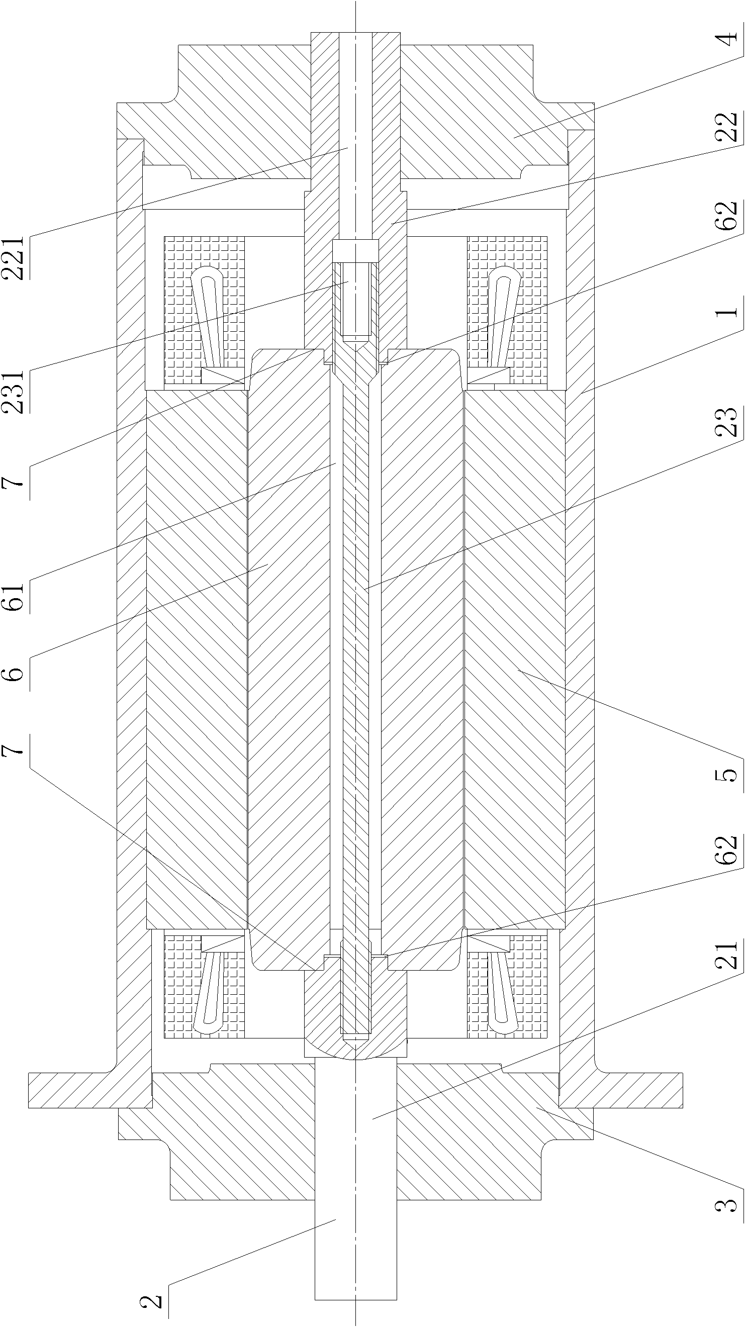
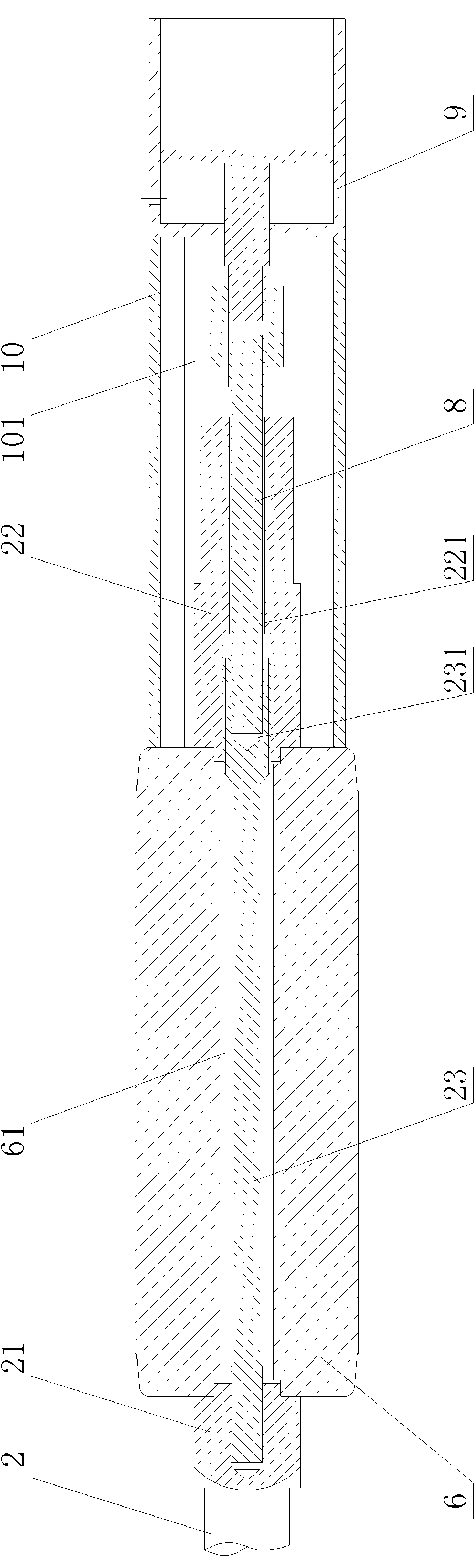
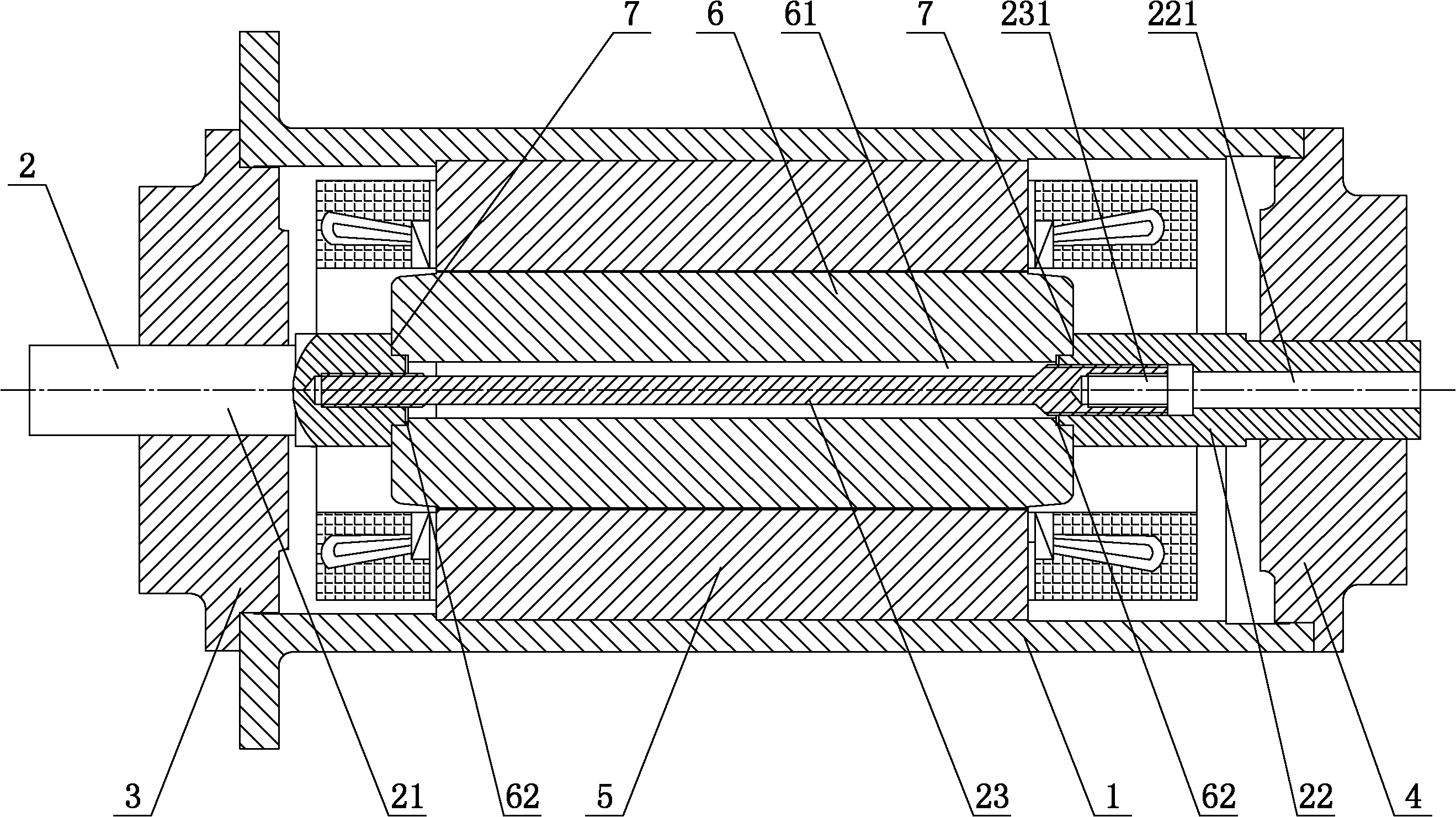
[0027] figure 1 A high-speed motor embodiment of the present invention is shown, the high-speed motor includes a motor housing 1, a motor shaft 2, a front flange assembly 3, a rear flange assembly 4, a motor stator 5 and a motor rotor 6, and the motor stator 5 Set in the motor housing 1, the motor main shaft 2 is placed in the motor stator 5, the motor main shaft 2 includes the front half shaft 21, the rear half shaft 22 and the tie rod 23, the tie rod 23 is sleeved in the inner hole 61 of the motor rotor 6, There is a gap between the pull rod 23 and the inner hole 61, the front end of the pull rod 23 is threaded with the front half shaft 21, the rear end of the pull rod 23 is threaded with the rear half shaft 22, and the front half shaft 21 and the rear half shaft 22 are tightened and clamped by the pull rod 23 It is held at both ends of the motor rotor 6, the front flange assembly 3 is installed on the front end of the motor housing 1, the front half shaft 21 is supported on...


PUM


Abstract

The invention discloses a high-speed motor, which comprises a motor casing, a motor main shaft, a motor stator and a motor rotor, wherein the motor stator is sleeved in the motor casing; the motor main shaft is arranged in the motor rotor and comprises a front half shaft, a rear half shaft and a pull rod; the pull rod is freely sleeved in an inner hole of the motor rotor; the front end of the pull rod is in threaded connection with the front half shaft; the rear end of the pull rod is in threaded connection with the rear half shaft; the front half shaft is tensioned with the rear half shaft by the pull rod; and the motor rotor is clamped between the front half shaft and the rear half shaft. The high-speed motor has the advantages of simple structure, convenient disassembly and assembly, convenient processing, large transmission torque and high critical rotation speed. The invention also discloses an assembly method of the high-speed motor.

Description

technical field [0001] The invention relates to the field of mechanical manufacturing, in particular to a high-speed motor and an assembly method thereof. Background technique [0002] High-speed rotating mechanical equipment is widely used in national defense, metallurgy, mining, chemical industry and other fields, such as various large fans, turbo compressors, ship power systems and centrifugal compressors. High-speed rotating machinery occupies an extremely important position in my country's national economy. [0003] Traditional high-speed rotating mechanical equipment mostly uses a transmission system (belt drive, gearbox drive, etc.) to achieve speed increase, and the power source is mostly an ordinary motor. Rotating mechanical equipment using this type of transmission mode allows a lower maximum operating speed. Due to the complexity of the transmission system, the vibration and noise are large during operation, there are many fault points, and the maintenance is mo...

Claims


Application Information

Patent Timeline
Patent Type & Authority Applications(China)
IPC IPC(8): H02K7/10H02K5/04H02K15/00
Inventor 熊万里蒋旭光罗春龙吕浪李芳芳
Owner FOSPOVA
Why Eureka
Try Eureka