

Electric shaking table
An electric shaker and shaker technology, applied in the field of electric shaker, can solve the problems of unsatisfactory shaking response and reduced production capacity, etc., and achieve the effect of simple and easy-to-understand control and remarkable effect
Inactive Publication Date: 2013-12-04
KUNSHAN JINXIN BIOTECH
View PDF0 Cites 0 Cited by
- Summary
- Abstract
- Description
- Claims
- Application Information
AI Technical Summary
Problems solved by technology
[0002] There are many kinds of shakers on the market, most of which are simple in structure but the response effect of shaking is not satisfactory, so people have to test the use effect of the shaker during use, which greatly reduces the production capacity, and a A shaker with simple manipulation and better shaking response effect has become an urgent need for people.
Method used
View moreImage
Smart ImageViewing Examples

Examples
Embodiment Construction
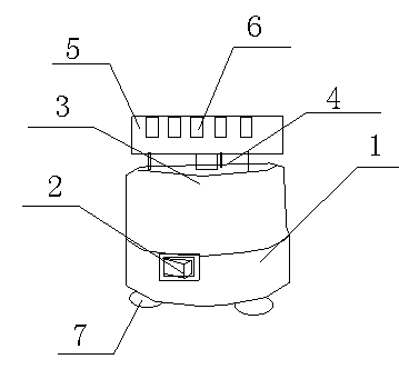
[0010] like figure 1 as shown in figure 1 As shown, an electric shaker includes a shaker main body 1, a control switch 2, a motor 3, a rotating shaft 4, a rotating platform 5, a test tube placement hole 6, and a base 7. The control switch 2 is arranged on the shaker main body 1, The motor 3 is arranged inside the shaker main body 1, the rotating shaft 4 is connected with the motor 3, the rotating platform 5 is connected with the rotating shaft 4, and the test tube placement hole 6 is arranged on the rotating platform 5 , the base 7 is arranged at the bottom of the shaker main body 1 .
Login to View More PUM
 Abstract
The invention discloses an electric shaking table comprising a shaking table main body, a shaking platform, a platform support and a control panel. The shaking platform is arranged on the shaking table main body, the platform support is arranged on the shaking platform; the control panel is arranged on the shaking table main body; the control panel is provided with an adjusting button, a control switch and a display screen; the display screen is arranged on the left side of the control panel; the control switch is arranged on the bottom of the control panel; and the adjusting button is arranged above the control switch. Advantages of the electric shaking table are that: operation method is simple and is easy to understand, and shaking effects are remarkable.
Description
technical field [0001] The invention relates to an electric shaker. Background technique [0002] There are many kinds of shakers on the market, most of which are simple in structure but the response effect of shaking is not satisfactory, so people have to test the use effect of the shaker during use, which greatly reduces the production capacity, and a A shaker with simple manipulation and better shaking response effect has become an urgent need for people. Contents of the invention [0003] The object of the present invention is to provide an electric shaker. [0004] The technical scheme adopted in the present invention is: [0005] An electric shaker, comprising a shaker main body, a control switch, a motor, a rotating shaft, a rotating platform, a test tube placement hole and a base, the control switch is arranged on the shaker main body, the motor is arranged inside the shaker main body, the The rotating shaft is connected with the motor, the rotating platform is ...
Claims
Login to View More Application Information
Patent Timeline
 Patent Type & Authority Applications(China)
IPC IPC(8): B01F11/00
Inventor 徐修甲王井义
Owner KUNSHAN JINXIN BIOTECH