
Circulating exhaust self-priming device

A technology of self-priming device and self-control exhauster, which is applied in the direction of machines/engines, non-variable pumps, driving pumps, etc., can solve problems such as high cost, difficulty in grid connection, and large volume of self-priming devices, and achieve low cost and adaptability Large-scale, small-volume effects

Inactive Publication Date: 2016-04-20
刘希元
View PDF10 Cites 0 Cited by
  • Summary
  • Abstract
  • Description
  • Claims
  • Application Information

AI Technical Summary

Problems solved by technology

Some water places must ensure water supply pressure and flow at any time, otherwise it will affect product quality and even cause production accidents
However, the synchronous self-priming pump has air in the water at the initial stage of pumping, resulting in low pump discharge pressure and difficulty in grid connection; the other is that the self-priming device is large in size and uses too much material, which makes its cost too high; and sometimes it is affected by the installation site. limits

Method used


Image

  • Circulating exhaust self-priming device
  • Circulating exhaust self-priming device
  • Circulating exhaust self-priming device

Examples


Embodiment Construction

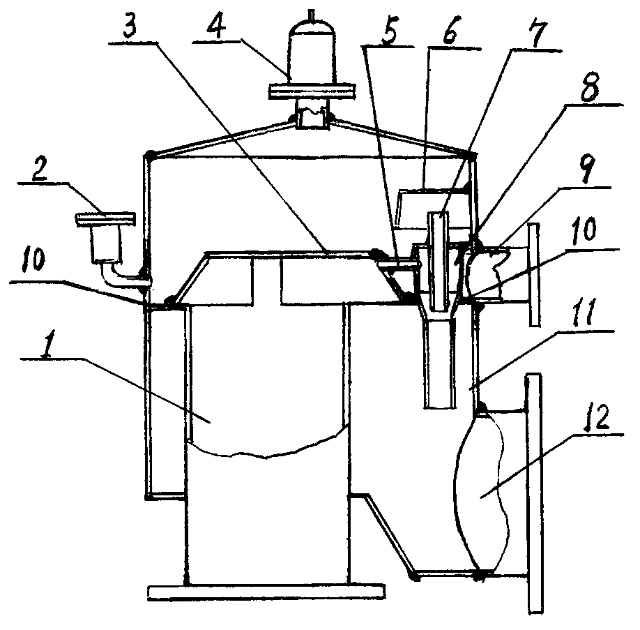
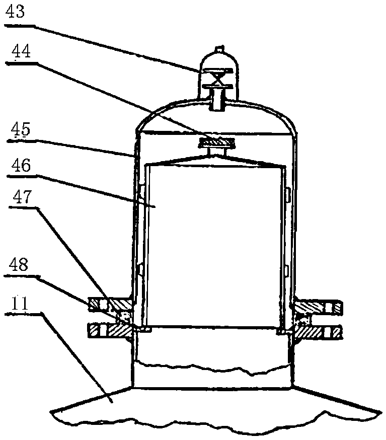
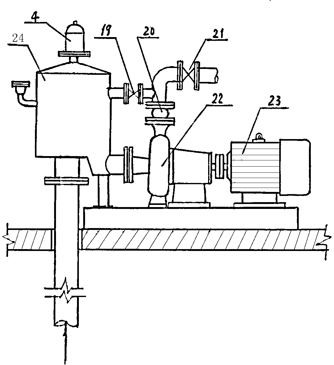
[0016] Such as figure 1 As shown, the circulating air exhaust self-priming device of the present invention includes a tank body 11, a water guide cap 3 and a partition 10 are arranged inside the tank body, and the water guide cap 3 and the partition plate 10 are welded to divide the tank body into upper and lower chambers , the top of the tank is equipped with a self-control air exhauster 4, the inside of the upper cavity of the tank is equipped with a return water windshield 6, the outer side of the upper cavity of the tank is connected with a water injection pipe gland 2, and the other side of the upper cavity of the tank is installed There is a circulating water inlet pipe 9, and a water outlet pipe 12 is arranged outside the lower chamber of the tank below the circulating water inlet pipe 9, and a water suction pipe 1 is arranged below the water guide cap 3, and the water suction pipe 1 passes through the air-inducing conduit 5 and the injector 8 Connected to each other, t...


PUM


Abstract

The invention relates to a self-suction device with air exhausted in a circulating mode. The self-suction device with the air exhausted in the circulating mode comprises a tank body. A water guide cap and separating plates are arranged in the tank body, a self-control air exhaust device is arranged on the top of the tank body, a backwater air blocking cover is arranged inside an upper cavity of the tank body, a water injection pipe gland is connected to one side of the outer portion of the upper cavity of the tank body, a circulation water inlet pipe and a circulation water outlet pipe are arranged on the outer portion of the upper cavity of the tank body, a water suction pipe is arranged below the water guide cap, the water suction pipe is communicated with an ejector through an air leading guide tube, the ejector enables the upper cavity and a lower cavity to be communicated, a backwater air leading ejecting pipe is arranged in the ejector, and the top portion of the backwater air leading ejecting pipe is arranged in the backwater air blocking cover. According to the self-suction device with the air exhausted in the circulating mode, air in the water suction pipe is sucked into the ejector through the air leading guide tube with the help of the pressure difference of the upper cavity and the lower cavity, the air further seeps and is mixed in the lower cavity, water is circulated up and down repeatedly in the self-suction device with the air exhausted in the circulating mode, and eventually all the air is exhausted to the nature through the self-control air exhaust device. The air is not contained in the water, the discharging pressure of a water pump rises naturally, and grid connection is carried out after the pressure reaches a standard.

Description

technical field [0001] The invention relates to a circulating exhaust self-absorbing device. Background technique [0002] Since the advent of synchronous self-priming pumps, many underground pump rooms have been eliminated one after another, completely eradicating the trouble of flooded pump rooms, and also making the pumps more convenient to maintain and use. Therefore, synchronous self-priming pumps have been widely used in recent years. However, with the continuous development of production technology, higher requirements have been put forward for production water supply. Some water places must ensure water supply pressure and flow at any time, otherwise it will affect product quality and even cause production accidents. However, the synchronous self-priming pump has air in the water at the initial stage of pumping, resulting in low pump discharge pressure and difficulty in grid connection; the other is that the self-priming device is large in size and uses too much ma...

Claims


Application Information

Patent Timeline
Patent Type & Authority Patents(China)
IPC IPC(8): F04D9/02
Inventor 刘希元
Owner 刘希元
Learn More