Crane Type Marine Cryogenic Fluid Filling Equipment

A low-temperature fluid and filling equipment technology, applied in mechanical equipment, equipment loaded into pressure vessels, cranes, etc., can solve problems such as difficulty in meeting user requirements, and achieve the effect of improving safety performance

Active Publication Date: 2015-08-26
连云港远洋流体装卸设备有限公司 +1
View PDF9 Cites 0 Cited by
  • Summary
  • Abstract
  • Description
  • Claims
  • Application Information

AI Technical Summary

Problems solved by technology

Filling liquefied natural gas (LNG, -162°), low-temperature ethylene (-104°) and other low-temperature media, unlike conventional fluid handling equipment, has special structural requirements for equipment, so common equipment is difficult to meet user requirements

Method used


Image

  • Crane Type Marine Cryogenic Fluid Filling Equipment
  • Crane Type Marine Cryogenic Fluid Filling Equipment
  • Crane Type Marine Cryogenic Fluid Filling Equipment

Examples


Embodiment Construction

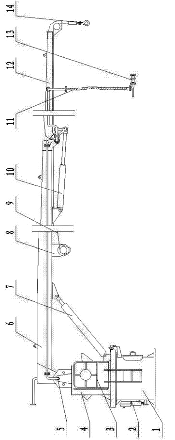
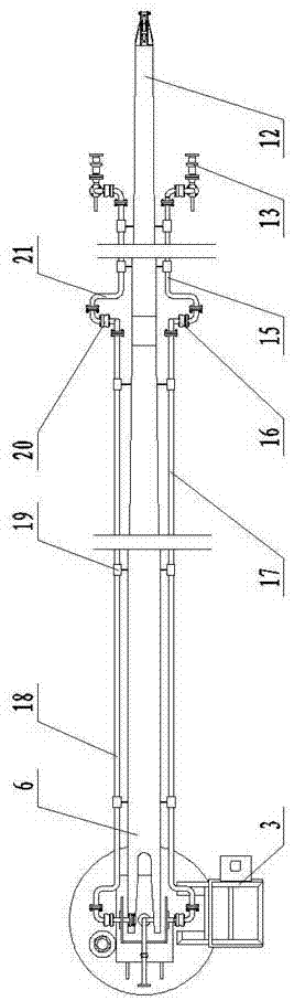
[0014] A crane-type marine low-temperature fluid filling equipment, including a base 1, a vertically arranged rotating column 4 is installed on the upper end of the base 1 through a slewing support, and a horizontally arranged hinge shaft 5 is installed above the rotating column 4 A main boom 6 is articulated, a main luffing mechanism 7 is arranged between the main boom 6 and the rotating column 4, and an auxiliary boom 12 is hinged at the front end of the main boom 6 through a pin shaft arranged parallel to the above-mentioned hinge shaft 5, An auxiliary luffing mechanism 10 is provided between the auxiliary boom 12 and the main boom 6, a fixed pulley is arranged at the outer end of the auxiliary boom 12, a hydraulic winch 8 is arranged in the middle of the main boom 6, and a hydraulic winch 8 A sling 9 is wound on the top, and the free end of the sling 9 bypasses the above-mentioned fixed pulley and is connected with a suspension hook 14; the left and right sides of the main ...


PUM


Abstract

The invention discloses a crane type marine cryogenic fluid filling device which comprises a base. A rotation pillar is arranged at the upper end of the base, a main suspension arm is hinged above the rotation pillar, and an auxiliary suspension arm is hinged to the front end of the main suspension arm. A fixed pulley is arranged on the outer end portion of the auxiliary suspension arm, and a hydraulic winch is arranged in the middle of the main suspension arm. A cable is twined around the hydraulic winch, and the free end of the cable winds around the fixed pulley and is connected with a lifting hook. According to the crane type marine cryogenic fluid filling device, horizontal rotation of the device can be achieved through the rotation pillar which is arranged on the base through a slewing bearing, the function of lifting weights by the device can be achieved through the main suspension arm arranged above the rotation pillar and hinged to an articulated shaft which is horizontally arranged. When rotation, amplitude variation and weight lifting are performed, the filling function of LNG is ensured and the utilization requirements of users are met at the same time. Meanwhile, by using an emergency pull-apart valve which is connected with a flexible pipe through a connecting short joint, safe separation between the flexible pipe and a groove ship can be achieved under special conditions, and the safety performance of the device is improved.

Description

technical field [0001] The invention relates to a low-temperature fluid filling device, in particular to a crane-type marine low-temperature fluid filling device. Background technique [0002] Filling equipment is used to complete the transmission of liquid medium between the shipping freighter and the wharf, and filling equipment is a key component on the wharf. Filling liquefied natural gas (LNG, -162°), low-temperature ethylene (-104°) and other low-temperature media is different from conventional fluid handling equipment, and has special structural requirements for equipment, so common equipment cannot meet user requirements. Contents of the invention [0003] The technical problem to be solved by the present invention is to propose a crane-type marine low-temperature fluid filling device with the functions of lifting heavy objects and LNG filling in view of the deficiencies of the prior art. [0004] The technical problem to be solved by the present invention is achi...

Claims


Application Information

Patent Timeline
Patent Type & Authority Patents(China)
IPC IPC(8): F17C5/02F16L27/08B66C23/16
Inventor 张洪道袁林明韩会林黄卫东王利民贺伟孙兰萍李新科王勇徐小婷李江
Owner 连云港远洋流体装卸设备有限公司
Why Eureka
Try Eureka