

Method and apparatus for reference signal processing
A technology of reference signal and processing method, which is applied in the field of communication and can solve problems such as reducing transmission efficiency
- Summary
- Abstract
- Description
- Claims
- Application Information
AI Technical Summary
Problems solved by technology
Method used
Image

Examples
Embodiment 1
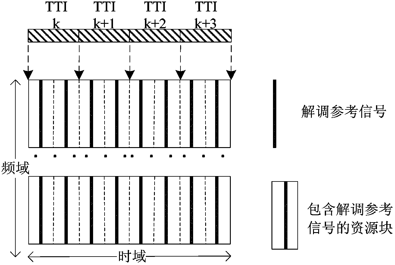
[0076] Figure 7 This is a first schematic diagram of sending a reference signal in a resource block pair according to an embodiment of the present invention.
[0077] In this example, in Figure 7 , the UE transmits in 4 consecutive TTIs, and the frequency domain positions of the resource block pairs in the 4 TTIs are the same. After reducing the number of demodulation reference signals, the number of demodulation reference signals in the resource block pairs in the kth, k+2 and k+3 TTIs remains unchanged, but there is no resource block pair in the k+1th TTI. A demodulation reference signal is sent. In the k+1 th TTI resource block pair, data is sent on the symbol used to send the demodulation reference signal to improve the spectral efficiency, or no data is sent to reduce the interference level of the demodulation reference signal of the neighboring cell.
[0078] At the receiving end, since the frequency domain positions of the resource block pairs in the 4 TTIs are the...
Embodiment 2
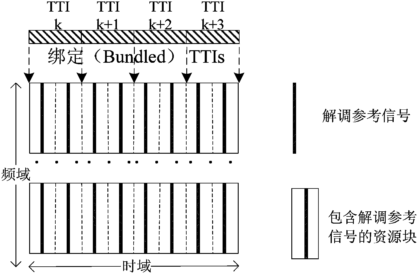
[0080] Figure 8 This is a second schematic diagram of sending a reference signal in a resource block pair according to an embodiment of the present invention.
[0081] exist Figure 8 , the UE transmits in 4 consecutive TTIs, and the frequency domain positions of the resource block pairs in the 4 TTIs are the same. The difference between the second embodiment and the first embodiment is that not only the kth, but also the number of demodulation reference signals in the resource block pairs in the k+2 and k+3 TTIs is unchanged, and the resource block pairs in the k+1th TTI are not changed. No demodulation reference signal is sent, and the symbol position of the demodulation reference signal in the resource block pair in the second slot in the kth TTI is moved backward, and the symbol position of the demodulation reference signal in the second slot in the kth TTI The symbol positions of the demodulation reference signals in the resource block pair are moved forward, so that t...
Embodiment 3
[0085] Figure 9 This is a third schematic diagram of sending a reference signal in a resource block pair according to an embodiment of the present invention.
[0086] exist Figure 9 In , the UE transmits in 4 consecutive TTIs, and the two resource block pairs in the two time slots in the TTI are in different positions, but there are resource block pairs with the same frequency domain position in different TTIs. Specifically, the first time slot in TTI k to TTI k+3 has the same frequency domain position of the resource block, and the second time slot has the same frequency domain position of the resource block.
[0087] In order to improve the spectral efficiency, the number of demodulation reference signals in the resource block pairs in TTI k and TTI k+2 remains unchanged, and the resource block pairs in TTI k+1 and TTI k+3 do not send demodulation reference signals, and TTI k+1 In the resource block pair in TTI k+3, data is sent on the symbol used to send the demodulatio...
PUM
 Abstract
Description
Claims
Application Information